
Busy Telephone line Indicator

The circuit described is designed to provide visual indicators for phone line usage, specifically for situations where simultaneous use of a modem or fax machine occurs alongside phone calls. It uses two light-emitting diodes (LEDs) to indicate the status of the phone line: a red LED (LED1) illuminates when the line is in use, while a green LED (LED2) indicates when the line is available. The circuit operates without requiring any external power supply, which enhances its versatility and ease of installation.
The design is built around a perf board, making it straightforward to assemble and mount within the housing of a phone. Key components include two NPN transistors (Q1, Q2 - 2N3392), which act as switches, controlling the LEDs based on the line's status. The bridge rectifier (BR1) converts the alternating current (AC) from the phone line into direct current (DC), allowing the LEDs to function correctly. The circuit also incorporates several resistors (R1 to R5) to limit current and ensure proper operation of the transistors and LEDs.
LED1 and LED2 are designed to flash in response to incoming calls, providing a visual cue that the phone line is active. Care must be taken during installation to avoid mixing the Tip and Ring connections, as the ring voltage can be substantial (between 90 to 130 volts). It is advisable to consult with the local phone service provider before installation, as regulations may vary by location and could necessitate an inspection.
If the circuit introduces distortion on the phone line, a 680-ohm resistor can be added in series with one of the incoming line wires and the bridge rectifier to mitigate this issue. This addition helps to ensure that the circuit operates effectively without compromising the quality of phone calls. Overall, this simple yet effective circuit can significantly enhance the functionality of a phone line used in conjunction with modems or fax machines.Have you ever been using the modem or fax and someone else picks up the phone, breaking the connection? Well, this simple circuit should put an end to that. It signals that the phone is in use by lighting a red LED. When the phone is not in use, a green LED is lit. It needs no external power and can be connected anywhere on the phone line, even mounted inside the phone.
Note: This circuit may cause problems for some when used. You may want to build a different circuit. This is a very simple circuit and is easily made on a perf board and mounted inside the phone. LED1 and LED2 flash on and off while the phone is ringing. Do not worry about mixing up the Tip and Ring connections. The ring voltage on a phone line is anywhere from 90 to 130 volts. Make sure no one calls while you are making the line connections or you'll know it. In some countries or states you will have to ask the phone company before you connect this to the line. It might even require an inspection. If the circuit causes distortion on the phone line, connect a 680 ohm resistor in between one of the incoming line wires and the bridge rectifier.
R1=3.3K 1/4 W Resistor R2=33K 1/4 W Resistor R3=56K 1/4 W Resistor R4=22K 1/4 W Resistor R5=4.7K 1/4 W Resistor Q1, Q2=2N3392 NPN Transistor BR1=1.5 Amp 250 PIV Bridge Rectifier LED1=Red LED LED2=Green LED Wire, Case, Phone Cord 🔗 External reference
Related Circuits
Commonly used 3-pin linear voltage regulators, such as the LM317, typically cannot handle input voltages exceeding approximately 30V. The LR8A from Supertex Inc is a new adjustable three-pin regulator that can accept input voltages up to 450V and can...
The circuit described can connect two telephones in parallel and function as a two-line intercom. Typically, a single telephone is connected to a telephone line. When another telephone is needed at a distance, a parallel line is utilized for...
The AD537 is a monolithic voltage-to-frequency (V-F) converter that includes an input amplifier, a precision oscillator system, an accurate internal reference generator, and a high-current output stage. A single external resistor-capacitor (RC) network is sufficient to configure any full-scale...
This circuit will allow you to connect any tape recorder that has a mic and remote input to a phone line and automatically record both sides of a conversation whenever the phone is in use. You will need to...
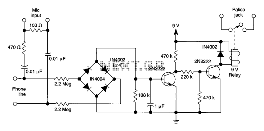
The DC voltage present on the telephone line typically ranges from 45 to 50V when on-hook and drops to approximately 6V when off-hook. This condition activates a step-down circuit relay, which in turn controls a tape recorder. Audio input...
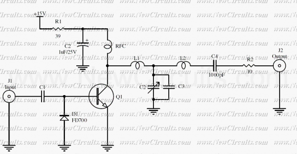
The RF circuit is a C-Class power amplifier. It is used in the last stage of transmitters. Its maximum power output is about 1 Watt. The circuit can be used in 3 frequency ranges: 30-100-200 MHz. More: The P-Out...