
Zener diode tester

The circuit utilizes the NE555 timer in an astable configuration, which continuously oscillates between high and low states, producing a square wave output. This output is fed into transformer T1, which steps up the voltage to a high level suitable for testing Zener diodes. The transformer is crucial for isolating the high voltage from the low voltage components, ensuring safety during operation.
Diode D1 plays a vital role in converting the high voltage AC output from the transformer into a pulsating DC voltage. The rectification process is essential for providing a stable voltage to the Zener diode under test. Capacitor C3 acts as a filter, smoothing out the pulsating DC to provide a more constant voltage level, which is necessary for accurate testing.
The current limiting resistors R2 and R3 are critical for protecting the Zener diode from excessive current, which could lead to damage or inaccurate readings. The selection of either resistor is facilitated by switch S2, allowing the user to choose between testing at 1mA or 2mA, depending on the specifications of the Zener diode being tested.
The digital multimeter, configured in DC voltage mode, is connected in parallel with the Zener diode. This setup enables the user to measure the voltage across the diode, which should correspond to the specified Zener voltage provided by the manufacturer. The circuit is designed to provide a simple yet effective means of testing Zener diodes, ensuring that they function within their specified voltage range. Overall, this circuit is a valuable tool for electronics enthusiasts and professionals alike, facilitating the testing and verification of Zener diode performance.Here is a very simple circuit that can be used for testing Zener diodes. The IC1 NE555 is wired as an astable multivibrator and the output of the IC is stepped up to a high voltage AC using the transformer T1. The unloaded AC voltage will be around 120V. The AC voltage is rectified by the diode D1 and filtered by the capacitor C3. This voltage is ap plied across the Zener diode through the current limiting resistors R2 or R3 which can be selected by switch S2 for testing the diode at 1mA or 2mA respectively. The digital multimeter in DC voltage mode is connected across the Zener diode under test. The Zener diode is a fine one; the meter will show the correct Zener voltage specified by the manufacturer.
🔗 External reference
Related Circuits
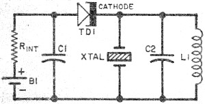
Leo Esaki invented the tunnel diode in 1957 while working at Sony (then known as Tokyo Tsushin Kogyo). Tunnel diodes feature a very narrow, heavily doped p-n junction approximately 10 nm wide, which exhibits a broken bandgap. This configuration...
Short circuits or broken PCB tracks can be easily identified using a multimeter; however, this tool may yield inaccurate results when testing the efficiency of a transistor or diode unless the component is unsoldered and removed from the PCB....

Having reliable connections is essential not only in daily life but also in electronics. Unlike social connections, the dependability of electrical contacts is crucial for the proper functioning of electronic devices. In the realm of electronics, the integrity of electrical...
The RF Tester (A3014) is a combination of four circuits designed to test various circuit concepts by implementing them and providing enhanced support circuits for their development. The Modulating Transmitter (A3014MT) replaces the previous Modulating Transmitter (A3001A) and allows...
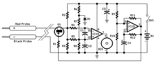
This small transistor tester employs a simple visual indication system to perform a quick go/no-go check on both NPN and PNP transistors. When testing a functioning NPN transistor, the green LED (D1) will flash, while the red LED will...

At the time, there was a desire to construct an ultimate continuity tester, leading to the creation of a wish list of required features. A genuine continuity tester is needed, as many multimeters and sounders react to resistances as...