
Quick On-Board Junction TesterCircuit

Both inputs of IC1A are connected together through two equal-value resistors (R4 and R5) and to half the voltage supply derived from the voltage divider formed by R2 and R3. Consequently, the same voltage appears at both input pins. Practically, half the voltage supply (approximately 4.5V) is present at the inverting input (pin #2) of IC1A, while a constant voltage generator composed of R6 and D1, which feeds the non-inverting input (pin #3) of IC1A via the voltage divider R7 and R8, clamps this pin to about 4.1-4.3V, keeping the output of the op-amp low. If the circuit input (the junction of R2 and R3) is shorted to negative ground (which simulates a shorted transistor junction), pin #2 of the op-amp will drop to 0V, and the voltage at pin #3 will decrease to approximately 0.3-0.35V due to the constant voltage generator. This condition will cause the op-amp output to go high, activating the piezoelectric sounder.
When a legitimate transistor or diode junction is connected to the circuit input instead of directly shorting the probes, the piezo sounder will emit a brief single beep as the probes make contact with a good junction. This is due to the time delay provided by the discharge of capacitor C2 while the voltage at pin #3 falls from about 4.1V to 0.3V. To enhance the signaling system, FET Q1, IC1B, and related components have been integrated. IC1B is configured as a 1Hz square wave generator, while Q1 functions as a solid-state switch, toggling on and off once per second, driven by the output of the op-amp. This arrangement connects and disconnects the junction of the device under test to the voltage-sensitive circuit built around IC1A once per second, resulting in a clearly audible series of short beeps indicating the condition of the junction or track under test.
The standard testing procedure involves placing the red probe on the base and the black probe on the emitter to hear a series of short beeps. If beeping does not occur, the junction may be broken or the transistor could be a PNP type. Maintaining the red probe on the base, the black probe should be moved to the collector, where a series of short beeps should again be heard. If not, the junction may be broken or the transistor could be a PNP type. Connecting the red probe to the emitter and the black probe to the collector should yield no output from the piezo sounder; the same applies when reversing the probes. An almost continuous beep would indicate a dead transistor.
When testing with the black probe on the base and the red probe on the emitter, a series of short beeps should be emitted. If not, the junction might be broken or the transistor could be an NPN type. Similarly, when the black probe remains on the base and the red probe is moved to the collector, a series of short beeps should be heard. If not, the junction may be broken or the transistor could be an NPN type. Connecting the red probe to the emitter and the black probe to the collector should yield no output from the piezo sounder, and the same should occur when reversing the probes. An almost continuous beep would indicate a dead transistor.
The testing procedure for common transistor types is similar, with the main difference being that when testing the base-emitter junction, a series of short beeps will be heard even after reversing the probes. This is due to the presence of resistors across either junction of the internal transistors forming a Darlington device. Another distinction arises from the internal diode connected across the emitter and collector (anode to emitter and cathode to collector) in these devices. In an NPN device, placing the red probe on the emitter and the black probe on the collector will produce the usual series of short beeps, but reversing the probes will yield no output from the piezo sounder. An almost continuous beep would indicate a dead transistor. PNP devices of this type are tested by reversing the probes, as previously described for common transistors. It is important to note that when testing the base-emitter junction, the beeps will be shorter compared to common transistors due to the measurement of two series junctions in Darlington configurations.
The testing procedure remains consistent for NPN silicon transistors (N-channel FETs) or PNP silicon transistors (P-channel FETs). The only variation occurs when checking the source-drain connections (corresponding to emitter-collector), where a faint sound will be heard if the device is good, even when reversing the probes. While these devices cannot be thoroughly tested with this tool, a MOSFET in good condition should not produce any beep when testing all junctions as explained for common transistors. However, a series of beeps will be emitted when checking the source-drain connection, with the red probe on the source and the black probe on the drain of an N-channel device, due to the presence of an internal diode, as described for Darlington transistors.
The beeping duration will be longer when testing germanium devices compared to silicon devices, attributed to the lower junction resistance of germanium. These devices cannot be thoroughly tested unless shorted, which would yield an almost continuous beep. However, this circuit can effectively distinguish between an SCR and a TRIAC. By placing one probe on the gate and the other on the cathode (or more accurately, the MT1 pin of a TRIAC), the tester will emit the usual series of beeps, even when the probes are reversed. In contrast, when testing an SCR, the series of beeps will occur when the probes are placed in one orientation but not when reversed.Short circuits or broken pcb tracks can be easily recognized by means of a Multimeter, but this tool can give wrong results when testing the efficiency of a transistor or diode, unless the device under test is unsoldered and removed from the pcb. A further shortcoming affecting such way of testing is the necessity to keep firmly the probes on the
pins of the device under test and at the same time to turn the head continually to read the Multimeter display. This device allows the user to concentrate on the (often problematic) pcb probes placement, because a short, a broken track, a good or burnt transistor or diode, will be signaled by a beep, as follows: A train of one-second lasting beeps spaced by a very short silence (in practice an almost continuous beep) indicates a shorted junction or, on the contrary, a good pcb track Both inputs of IC1A are connected together by two equal value resistors (R4 and R5) and to half the voltage supply obtained by means of the voltage divider R2 and R3.
So, the same voltage should be present at both input pins. In practice, half the voltage supply (i. e. about 4. 5V) will be present at the inverting input (pin #2) of IC1A, but the constant voltage generator formed by R6 and D1, feeding the non-inverting input (pin #3) of IC1A by means of the voltage divider R7 and R8, clamps this pin to about 4. 1 - 4. 3V: this will cause the output of the op-amp to stay low. If the circuit input (R2 to R3 junction) is shorted to negative ground (a condition equivalent to a shorted transistor junction) pin #2 of the op-amp will go to 0V and the voltage at pin #3 will decrease to about 0.
3 - 0. 35V (caused by the constant voltage generator mentioned above): the op-amp output will go high, activating the piezoelectric sounder. When a real transistor or diode junction is connected to the input of the circuit instead of shorting the input probes directly, the piezo sounder will emit only a short single beep just as the probes will come in contact with a good junction, due to the time delay provided by the discharge of C2 when the voltage at pin #3 is falling from about 4.
1V to 0. 3V. To provide a better signaling system, Fet Q1, IC1B and related components were added. This op-amp is wired as a 1Hz square wave generator and Q1 acts as a solid-state switch, going on and off one time per second having the Gate driven by the op-amp output. In this way, the junction of the device under test is connected and disconnected to the voltage sensitive circuit built around IC1A one time per second and the result will be a clearly audible train of short beeps signaling the good condition of the junction or track under test.
Place the Red probe on the Base and the Black probe on the Emitter: a train of short beeps should be heard. If not, the junction is broken or the transistor is a PNP type. Always holding the Red probe on the Base, shift the Black probe to the Collector: a train of short beeps should be heard.
If not, the junction is broken or the transistor is a PNP type. Placing the Red probe on the Emitter and the Black probe on the Collector should cause no output from the piezo sounder: the same should occur when reversing the probes. On the contrary, if an almost continuous beep is heard, the transistor is dead. Place the Black probe on the Base and the Red probe on the Emitter: a train of short beeps should be heard.
If not, the junction is broken or the transistor is a NPN type. Always holding the Black probe on the Base, shift the Red probe to the Collector: a train of short beeps should be heard. If not, the junction is broken or the transistor is a NPN type. Placing the Red probe on the Emitter and the Black probe on the Collector should cause no output from the piezo sounder: the same should occur when reversing the probes.
On the contrary, if an almost continuous beep is heard, the transistor is dead. The procedure is similar to that adopted for common transistor types. The main difference is that when testing the Base - Emitter junction, you will hear the train of short beeps even after reversing the probes. This occurs because a couple of resistors is always present across either junction of the two internal transistors forming a Darlington device.
The second difference is due to the fact that an internal diode connected across Emitter and Collector (Anode to Emitter and Cathode to Collector) is always present in these devices. Therefore, with a NPN device, placing the Red probe on the Emitter and the Black probe on the Collector you will hear the usual train of short beeps, but when the probes are reverted there will be no output from the piezo sounder.
On the contrary, if an almost continuous beep is heard, the transistor is dead. PNP devices of this type are tested reversing the probes, as explained above for common transistors. Please note that when testing the Base - Emitter junction the beeps will be shorter compared to common transistors. This is caused by the fact that two junctions in series are to be measured when testing Darlingtons. The testing procedure is the same as that adopted for NPN silicon transistors (N-Channel FETs) or PNP silicon transistors (P-Channel FETs).
The only difference is shown when checking Source - Drain connections (corresponding to Emitter - Collector): a faint, blurring sound will be heard if the device is good, even reversing the probes. These devices cannot be thoroughly tested with this tool, but a MosFet in good condition should cause no beep to be heard when testing all junctions as explained above for common transistors.
But the usual train of beeps will be emitted when checking the Source - Drain connection, placing the Red probe on the Source and the Black probe on the Drain of a N - Channel device, because the presence of an internal diode, as explained above for Darlington transistors. Use the same testing procedure adopted for silicon transistors. The beeps forming the train will last longer than when testing silicon devices: this is due to the lower junction resistance of germanium devices in respect to silicon types.
These devices cannot be tested thoroughly, unless they are shorted: in this case an almost continuous beep will be heard. But this circuit can be useful to distinguish a SCR from a TRIAC. Placing a probe on the Gate and the other probe on the Cathode or, more properly, the MT1 pin of a TRIAC, the Tester will emit the usual train of beeps, even reversing the probes.
When testing a SCR, the train of beeps will occur when the probes are placed in one way and not when reversed. 🔗 External reference
Related Circuits
The charger is built around a LM317 adjustable regulator. The charge starts when a battery is connected between pins JP1-JP4 or JP2-JP4 or JP3-JP4. For example, if a battery is connected to JP1-JP4 pins then the current that flows...
The Reaction Capability Tester is utilized to assess and enhance an individual's quick-response abilities. It features various designs, with the depicted model comprising a CD4017 decimal counter and a light-emitting diode (LED). The construction of the Reaction Capability Tester...
Eight solid-state relays (SSR) and an ADAM-4068 (Serial-I/O device) are utilized to wire a circuit for controlling a motor in a robotic application. The ADAM-6048 is a versatile device that facilitates control of digital inputs and outputs via RS-485...
The single-junction transistor is commonly utilized in sawtooth and pulse generators, and it can also be configured to create a basic sine wave generation circuit. As an oscillator circuit composed of discrete components, it requires a minimal number of...
Acoustic check of transistor and diode junctions. Also suitable as a continuity tester. Short circuits or broken PCB tracks can be easily recognized. The acoustic check of transistor and diode junctions is a method used to assess the functionality of...
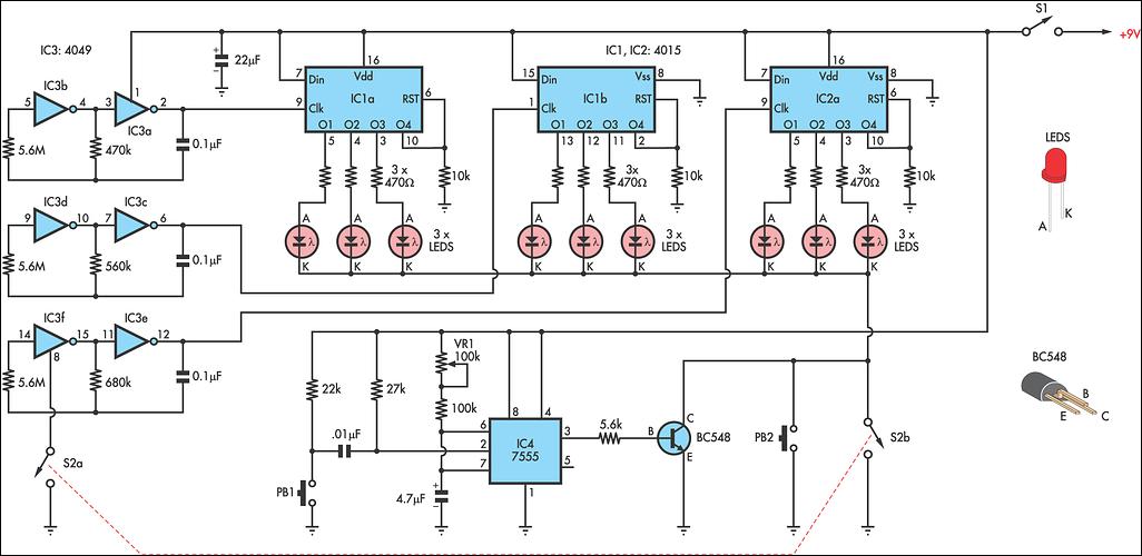
This circuit is a toy designed to help young children learn to count. Power is activated by switch S1, followed by closing switch S2, which causes nine LEDs to flash slowly. When S2 is opened, the LEDs turn off....