
Zone Alarm System

The circuit operates on a simple delay mechanism facilitated by the charging of capacitor C6 through resistor R11. The time delay can be tailored to suit specific requirements by adjusting the capacitance of C6 or the resistance of R11, allowing for flexibility in system configuration. The illumination of LED6 serves as a critical status indicator, providing users with a clear visual cue that the alarm system is ready and operational.
The re-entry switch is a crucial component designed to enhance user convenience while maintaining security. By discharging C6, it effectively resets the timing mechanism, allowing users to enter the premises without triggering the alarm. The choice of a concealed reed switch for this function ensures that it remains discreet and secure, preventing unauthorized access while still providing a means for legitimate entry.
The panic switch adds an additional layer of security, enabling immediate activation of the alarm in emergency situations. This feature is particularly valuable in scenarios where rapid response is necessary. The relay contacts, RLA1 and RLA2, are integral to the alarm's operation; RLA1 maintains the circuit's state once the alarm is triggered, while RLA2 activates the audible alarm, alerting individuals in the vicinity of a potential security breach.
Overall, this circuit design emphasizes both user-friendly operation and robust security measures, ensuring that the alarm system functions effectively while accommodating the needs of the user.At switch on, C6 will charge via R11, this acts as the exit delay and is set to around 30 seconds. This can be altered by varying either C6 or R11. Once the timing period has elapsed, LED6 will light, meaning the system is armed. LED6 may be mounted externally (at the bell box for example) and provides visual indication that the system has set. On ce set any contact that opens will trigger the alarm, including Zone 1. To prevent triggering the alarm on entry to the building, the concealed re-entry switch must be operated. This will discharge C6 and start the entry timer. The re-entry switch could be a concealed reed switch, located anywhere in a door frame, but invisible to the eye.
The panic switch, when pressed, will trigger the alarm when set. Relay contacts RLA1 provide the latch, RLA2 operate the siren or buzzer. 🔗 External reference
Related Circuits
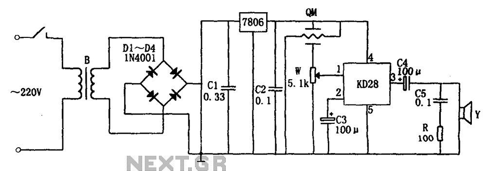
The system includes a gas-sensitive sensor element QM (type QM-N5), a buck rectifier, and regulator circuits, integrated circuits KD28, a speaker Y, and other components. The buck regulator circuit features a transformer rectifier and a bridge rectifier comprising diodes...
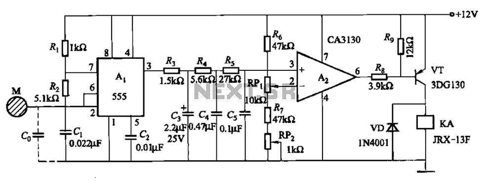
The circuit utilizes a 555 IC in conjunction with capacitors C1, C2, and a metal plate (tablet) M to create a distributed capacitance Co and resistor R1 connected to ground. Resistor R2 forms a self-excited multivibrator, while resistors R3...
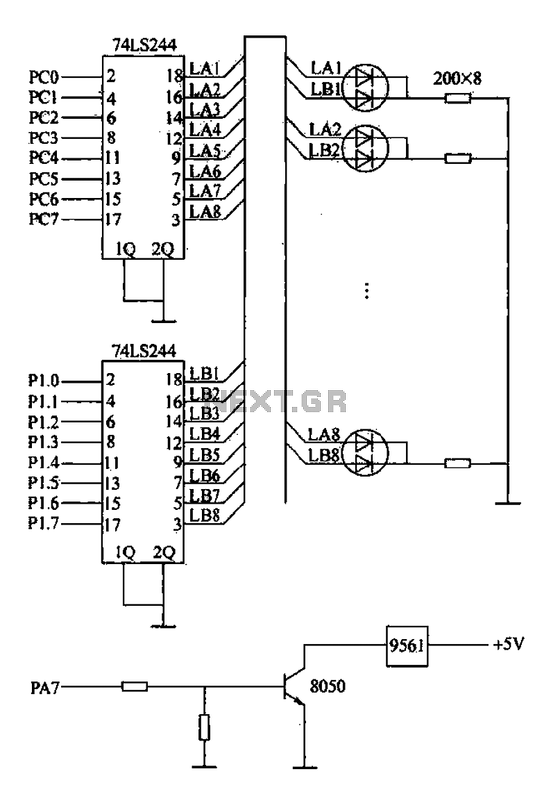
Alarm interface circuitry featuring a two-color light-emitting diode (LED) display. When LAi is at a high level and LBi is low, the green LED lights up; conversely, if LAi is low and LBi is high, the red LED lights...
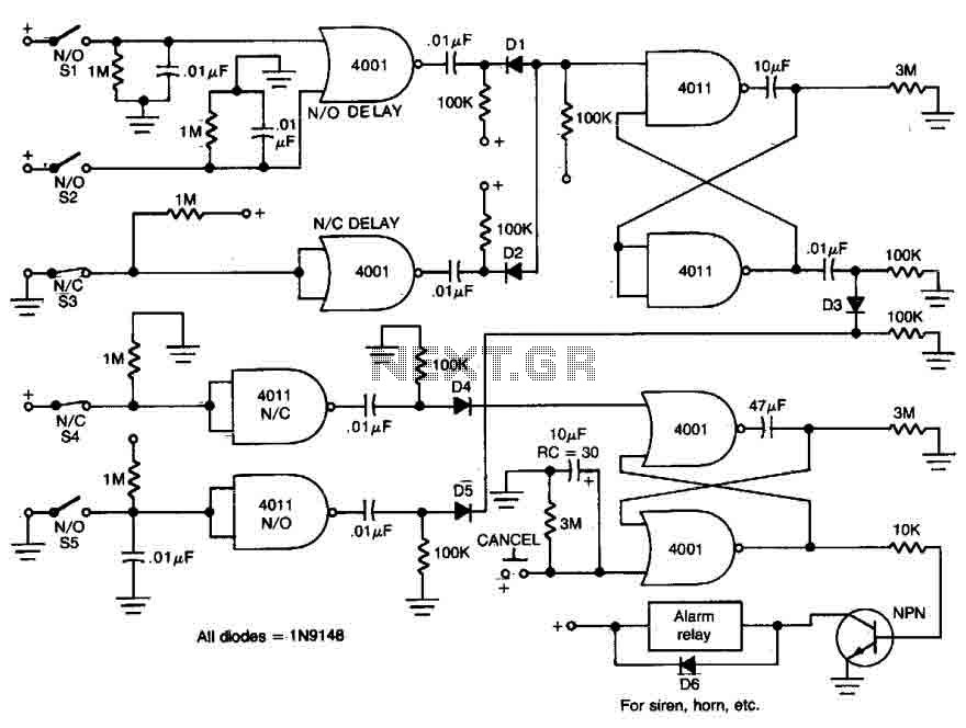
This circuit features open and closed loop contacts (switches 1, 2, 3) that activate the alarm, which remains on for a duration of 5 to 10 minutes. The triggering delay for entrance and exit is set to 27 seconds....
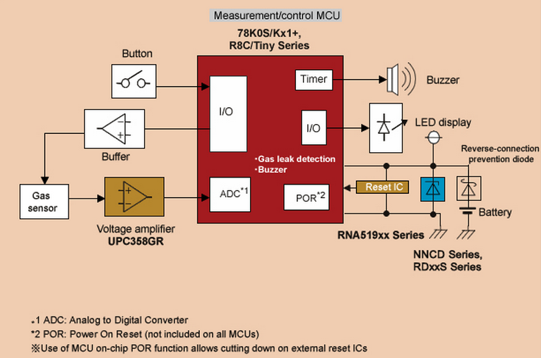
When a gas leak occurs, a gas leak alarm must detect the problem immediately and issue an alarm. The gas detection sensor typically used in these types of alarms sends an amplified signal from the sensor to the controlling...
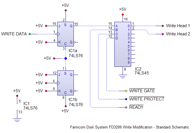
Install the new mod board into the FDS drive mechanism. This involves cutting two traces and soldering eight wires to various points on the board. If prior experience with console modchips exists, this task should be straightforward. The Famicom's...