
8-bit bus control widely used 12-bit DA converter Universal

The circuit described facilitates the integration of an 8-bit microcomputer with digital-to-analog (D-A) converters, specifically the DAC80-CB model. This converter is designed to handle both binary and BCD inputs, offering versatility in applications where different digital formats are utilized. The architecture necessitates a careful arrangement of data latches to manage the flow of information effectively. The low byte (LB), composed of D4 to D7, is crucial for initial data storage, while the high byte (HB) is responsible for interfacing with the D-A converter.
Timing is critical in this configuration; the clock pulse must trigger the data latches simultaneously to prevent errors. This synchronous operation ensures that the data integrity is maintained during transitions from parallel to serial formats. The DAC80-CB converter outputs a voltage based on the binary input received, with the reference voltage set at 6.3V. This reference voltage is essential for establishing the output range and accuracy of the D-A conversion.
The removal of jumper TR from the outer Hz input indicates a configuration choice that may be required under specific operating conditions, potentially allowing for different clock frequencies or modes of operation. The ability to connect multiple DACs in a tracking configuration enhances the system's capability to manage complex signal processing tasks, although it does introduce additional costs.
For applications requiring bipolar output, the option to short-circuit jumper JZ facilitates the adjustment of output characteristics, enabling the internal resistance to be set at 6.3kΩ, which supports a current flow of 1mA. This feature is particularly beneficial in scenarios where precise control of output voltage is necessary, allowing for greater flexibility in circuit design and implementation. Overall, this schematic design provides a robust framework for interfacing microcomputers with D-A converters, ensuring efficient data handling and accurate signal generation.8 microcomputer data is 8-bit parallel output, in addition to the serial input of D -A converters, in general, have to enter the data into two groups, and to Chen whole. Requir ements for the data latch 16 straight odd first D7 ~ D4 the four data latch in the low byte (LB); commission next clock pulse at the same time (not on the table at the same time generate an error) to fermium have been stored 4 data and high byte (HB) given away 12 D. A converter. DAC80-CB is king -.V binary input voltage output DA converter din - (in addition to BCD code input and current output type), the reference voltage i was 6.
3V, connected to the REF-IN terminal. Also the jumper tr, removed from the outer Hz input. When the need to use multiple DAC, the circuit has a tracking feature, much more expensive than using this method o BP bipolar partial set terminal, if the output voltage bipolar can be jumper JZ short circuit, the internal resistance make 6.3kO 1mA current flows.
Related Circuits
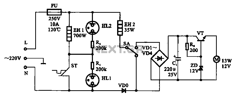
The electric thermos temperature detection control circuit is designed to monitor and manage the temperature within an electric thermos. It primarily consists of a control circuit for the boiler heater and heater insulation, an electrical magnetic pump motor drive...
The ADRF6702 TxMod is an IQ modulator that includes an integrated phase-locked loop (PLL) and voltage-controlled oscillator (VCO). The PLL synthesizer employs a fractional-N PLL to produce a 2*FLO input for the I-Q modulator. The PLL reference input can...
Neural networks are a broad topic. This example demonstrates how to create a basic neural sensor that takes resistive readings from multiple sensors, multiplies them by a weight factor, and then sums the results. The results are compared to...
For beginners experiencing similar challenges, a general-purpose I/O board is recommended to minimize prototyping time and maximize space on the breadboard for projects. The construction of this board is straightforward. Basic I/O devices can be soldered onto a general-purpose...
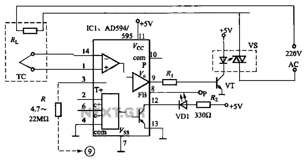
An automatic electric furnace temperature controller is depicted in FIG. 1-25. The closed circuit is established through a temperature detection output control loop. As the temperature rises, the output voltage increases. When the voltage reaches a preset temperature value,...
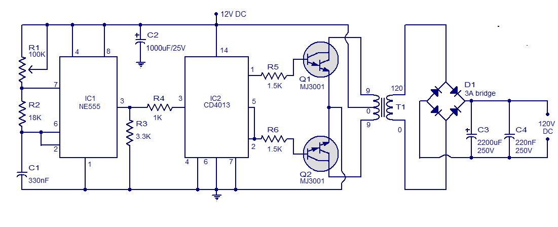
This is a simple circuit designed to convert 12V DC to 120V DC. The circuit comprises two main phases: the inverter stage and the rectifier and filter stage. The NE555 integrated circuit (IC1) is configured as an astable multivibrator,...