
Electric Oven automatic temperature controller
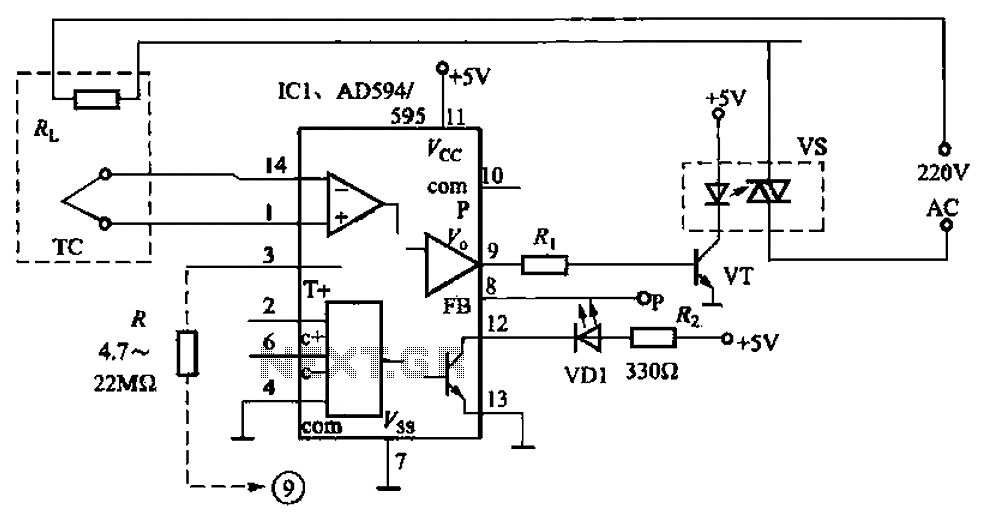
The automatic electric furnace temperature controller operates as a feedback system, utilizing a thermocouple (TC) for precise temperature measurement. The TC generates a voltage output proportional to the temperature, which is fed into an integrated circuit (IC1) that contains a differential amplifier. The differential amplifier compares the TC output voltage against a reference voltage set by an external resistor divider network. As the temperature rises, the output voltage from the differential amplifier increases until it reaches a threshold level defined by the set point. At this juncture, the output to the solid-state relay (VT) is interrupted, effectively stopping the heating process.
The solid-state relay is employed for its rapid switching capabilities and durability compared to mechanical relays. It connects to the heating element (RL), which is typically a resistive load. As the temperature drops below the set point, the TC's voltage output decreases, prompting the differential amplifier to reactivate the solid-state relay, thus restarting the heating cycle.
The hysteresis feature, adjustable via the resistor (R), prevents rapid cycling of the heating element by introducing a temperature band within which the system will not react to minor fluctuations. This is crucial for maintaining a stable temperature and prolonging the lifespan of the heating element and relay.
The controller also integrates alarm functionality through designated pins, which can signal the status of the system. The open transistor configuration allows for direct interfacing with visual or auditory indicators, such as LEDs or buzzers, enhancing user awareness of the system's operational state. The inclusion of a zero offset circuit in the AD594/595 may provide additional calibration capabilities, ensuring accurate temperature readings under varying conditions, although it is not utilized in this specific design.
Overall, the automatic electric furnace temperature controller exemplifies an efficient and reliable method for managing heating processes, suitable for various industrial and laboratory applications. Automatic electric furnace temperature controller shown in FIG. 1-25. The closed circuit is formed from a temperature detection output control loop; the temperature rises, the output voltage increases when the voltage increases to a preset temperature value, the output stop, stop heating; trans, the temperature is lowered, when reduced to the pre when the set temperature, and automatically starts heating. TC thermocouple directly connected to IC1 s O, ? feet, sending internal differential amplifier, the output from a foot, driven by solid state relay vs VT conduction, plus hot wires RL ohmic heating, when heated to a preset temperature, output is stopped.
pin input and output hysteresis setting, connected to a pin through resistor R to achieve, the smaller the resistance value, the greater the hysteresis. Controlling the temperature of the high and low foot by pressing decisions relations pin voltage and temperature, TC between as shown in Table 1-3.
AD594/595 is also designed with zero offset circuit (not used here). ?, ? pin alarm, indicating the output of the internal as c, e very open transistor can directly drive LED or small relays, access here VD1 as the working lights for indicating the start and stop on heating.
Related Circuits
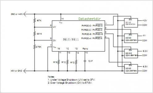
The PS10 saves board space, improves accuracy, eliminates optocouplers or level shifts, and reduces overall component count by combining four programmable timers, input under-voltage (UV) and over-voltage (OV) supervisors, a programmable power-on reset (POR), and four 90V open drain...
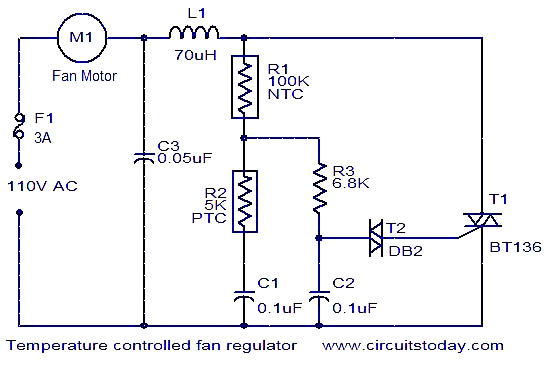
This fan regulator circuit automatically controls the speed of a fan based on temperature. It utilizes two thermistors (R1 and R2) for temperature sensing. The operation is similar to previously published designs, with thermistors replacing the potentiometer. As the...
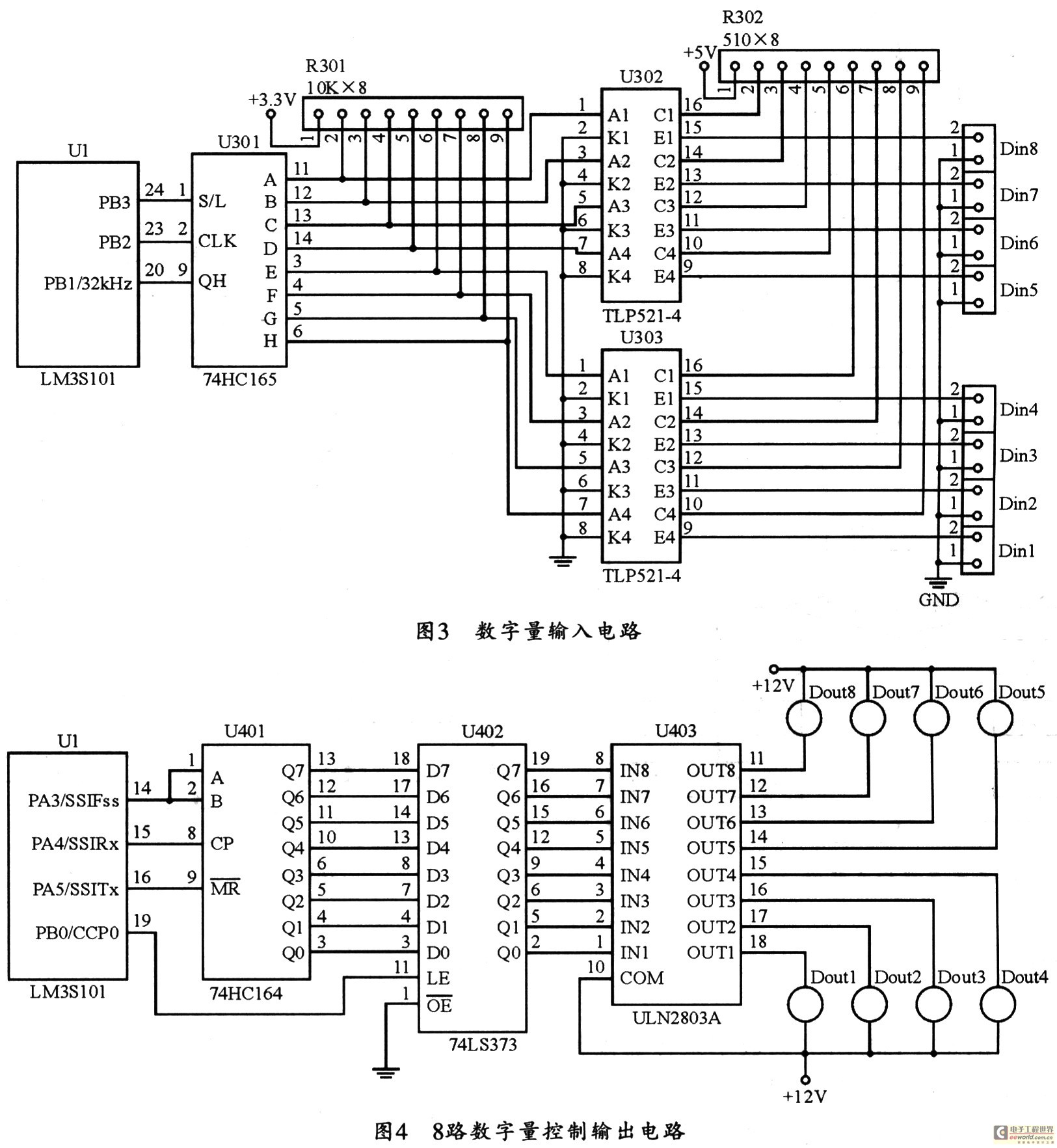
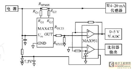
The figure utilizes a controller as the primary equipment for gathering and controlling digital data within an on-site monitoring system. The stability of on-site control operations is crucial to the overall system performance. Therefore, a simple and stable structure...
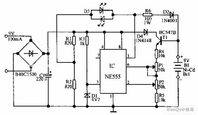
An automatic Ni-Cd battery charger circuit is depicted in the provided image. The internal comparator of the NE555 timer is configured to a reference voltage of 4.7V using a Zener diode. When the voltage at pin 6 exceeds this...
Field bus technology and intelligent instrument technology are currently two of the most rapidly evolving technologies in automation and control. In the realm of field bus technology, the CAN bus has established itself as a relatively fast communication standard...
Standard serial interfacing of a microcontroller (TTL) with a PC or any RS232C standard device requires a TTL to RS232 level converter. A MAX232 is used for this purpose. It provides a 2-channel RS232C port and requires external 10µF...