
Use neural sensors to build smart sensor systems using microcontrollers
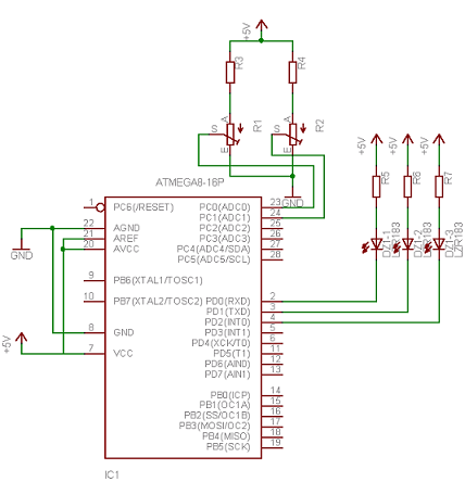
A neural sensor circuit can be designed using an Atmega8 microcontroller (MCU) to illustrate the principles of a basic neural network. The circuit employs two potentiometers as input sensors, which provide variable resistance based on the environmental conditions, such as light intensity or temperature. Each potentiometer's resistance is read by the MCU's analog-to-digital converter (ADC), converting the analog voltage levels into digital values that the microcontroller can process.
The two input values are then multiplied by pre-defined weight factors, which can be adjusted to simulate different sensitivities for each input. This multiplication is performed in the MCU using simple arithmetic operations. The weighted inputs are summed together to produce a single output value.
This output value is then compared against three predetermined threshold levels. These thresholds define the conditions under which the output state of the neuron changes. For instance, if the summed output value is below the lowest threshold, the neuron may indicate a low-light condition. If it falls between the two middle thresholds, it may indicate a medium-light condition, and if it exceeds the highest threshold, it indicates a high-light condition.
The outputs of the neuron are represented by three LEDs, each corresponding to one of the three states. The MCU controls these LEDs based on the comparison results. If the output indicates low light, the first LED will light up; for medium light, the second LED will illuminate; and for high light, the third LED will be activated.
The circuit can also be programmed to implement actions based on the light conditions detected. For example, when in low light, the system might activate a sleep mode to conserve power. In medium light, it could direct the robot to move toward brighter areas, and in high light, it could initiate solar charging.
To simulate this behavior, the VMLAB simulator can be utilized, allowing for the testing and visualization of the circuit's operation without the need for physical components. The simulation will showcase how the inputs affect the outputs and how the system responds to varying environmental conditions, effectively demonstrating the functionality of a basic neural sensor.Neural networks are wide topic. But this small example demonstrates how to create basic neural sensor which takes resistive readings from multiply sensors and multiply it by wight factor and then sum the results. Results are compared to three level threshold. Without going too deep in to neural networks we can say, that neural cell thresholds are similar to natural biological neurons. For instance pain levels: itch is low level of pain while burning sensations is combined of ice cold and warm sensations. Neural sensors can operate in the same way. Lets take typical neural sensors which consists of two inputs with some weights and three outputs. Depending on threshold level that sum of inputs gives a‚¬ we have and output signal on one of three outputs.
Lets build real world neuron with two inputs and three outputs. As sensor I will use potentiometers which can be replaced by photocells or temperature sensors. According to these two sensor readings neuron can have three states: this could be like low light, medium light and high light, o low temp and so on. If you will decide to put neuron to your robot, this could be used for solar cell charging like if its is dark, go to sleep mode, if it is medium light go to brightest area, if it is high light level, stop and start charging.
Above schematic is simple neuron sensor simulator made of Atmega8 MCU couple potentiometers and three LEDs. Lets write simple routine to simulate this embedded neuron. For simulation I used VMLAB simulator. 🔗 External reference
Related Circuits
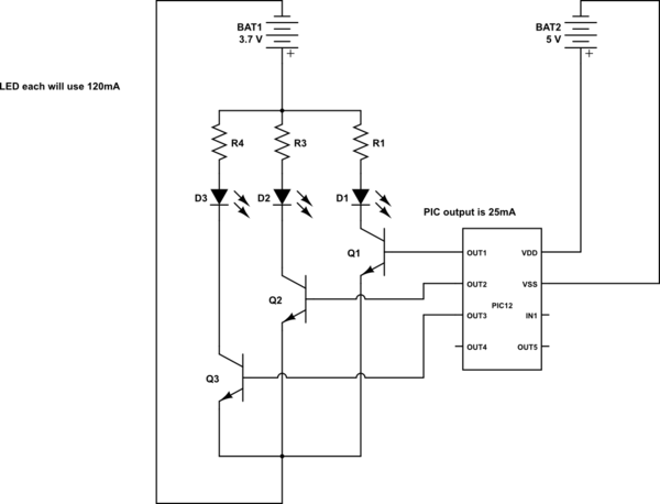
This is a conceptual schema utilizing a PIC12 microcontroller to control the blinking of three LEDs, each exhibiting different blinking patterns. There are several questions that need to be addressed. The circuit design involves a PIC12 microcontroller, which is a...
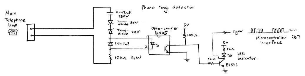
This circuit detects the dial tone from a telephone line and decodes the keypad pressed on the remote telephone. The dial tone heard when picking up the phone is referred to as Dual Tone Multi-Frequency (DTMF). This name originates...
One of the most effective communication methods to be implemented in a digital system is the use of the RS232 serial line. The microcontroller 89S51 is equipped with a UART, allowing it to perform serial communication at RS232 levels...
Numerous circuits are available for infrared burglar alarms; however, the transmitter section of these circuits can be complex and may require assembly. This burglar alarm circuit utilizes a standard DVD remote as the transmitter, which reduces both cost and...
Upon entering the password, the application, in this case "LED," will illuminate. In this digital locking system project, the interfacing of a keypad and a 16x2 LCD with a microcontroller will be explored, along with the accompanying code. This...
Build a 20 Amp 13.8 Volt Power Supply. There are some electronic applications where it may be necessary to run relatively high current circuits, such as transformers. To construct a 20 Amp, 13.8 Volt power supply, the following components and...