
555 audio oscillator circuit diagram of a radio-frequency drive
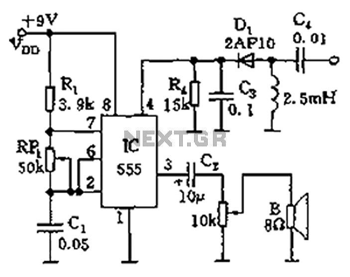
The circuit utilizes a 555 timer configured in astable mode to generate audio frequencies. The resistors R1 and RP1, along with capacitor C1, set the timing intervals that define the output frequency. The frequency of oscillation can be fine-tuned by adjusting the variable resistor RP1, allowing for a broad range of audio outputs suitable for various applications, such as tone generation or sound signaling.
The reset functionality of the 555 timer is crucial for controlling the oscillator's operation. When pin 4 receives a low signal, the timer is reset, halting any oscillation. This feature is particularly useful in scenarios where the circuit must remain inactive in the absence of an RF signal. The presence of an RF signal is detected by diode D1, which rectifies the incoming signal and applies a voltage to pin 4. If this voltage exceeds the threshold of 1V, it enables the oscillator, producing a continuous audio tone through the speaker.
Overall, this circuit exemplifies a simple yet effective method for generating audio signals based on external RF input, leveraging the versatile capabilities of the 555 timer IC. The design can be employed in various applications, including alarms, sound effects, and communication devices where audio signaling is required.As illustrated, 555 and R1, RP1, C1 and other components controlled audio oscillator, f frequency of 1.44/(R1 + 2RP1) C1, illustrated parameters between 600Hz ~ 20kHz, can be s elected by adjusting the RP1. The oscillator or not, depending on the reset terminal 4 foot level. When no RF signal, 4 feet was low, 555 state to stop vibration; when a designated radio frequency signal, the detector diode detector D1, the video signal is applied to pin 4, when the signal level is higher than 1V, the start-up, the speaker will be issued tone given audio signal
Related Circuits
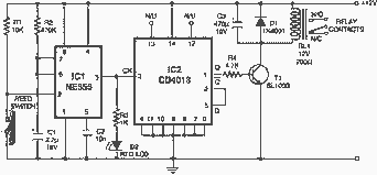
Here is an interesting circuit for a magnetic proximity switch which can be used in various applications. The magnetic proximity switch circuit, in principle, consists of a reed switch at its heart. When a magnet is brought in the...
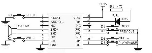
This tutorial focuses on the MP3 mode of the WTV020SD-16P module. With this straightforward circuit, AD4 format music files can be played. A video demonstration of this simple project is available at the end of the article. The project...

This is the design circuit diagram of an ultrasonic mosquito repeller. The circuit operates based on the theory that insects, such as mosquitoes, can be repelled by sound frequencies in the ultrasonic range (above 20 kHz). The circuit utilizes...
A circuit that utilizes one cycle of alternating current (AC) to produce direct current (DC). A half-wave rectifier circuit generates DC from either the positive or negative cycle of the AC input, but not both. It is important to...
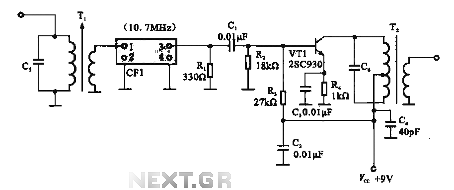
This circuit features a ceramic filter integrated with an FM intermediate frequency (IF) amplifier. The FM IF amplifier circuit primarily consists of an input variable voltage regulator (T), ceramic filters (CF1), and additional components such as the IF amplifier...

The TBA120 Series integrated circuits (ICs) offer a high-gain limiting intermediate frequency (IF) amplifier and a quadrature coincidence detector in a single package. These ICs are primarily designed for the extraction of television intercarrier sound, which is frequency modulated...
Warning: include(partials/cookie-banner.php): Failed to open stream: Permission denied in /var/www/html/nextgr/view-circuit.php on line 713
Warning: include(): Failed opening 'partials/cookie-banner.php' for inclusion (include_path='.:/usr/share/php') in /var/www/html/nextgr/view-circuit.php on line 713