
Half-Wave Rectifier Circuit
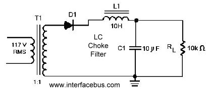
The half-wave rectifier circuit is a fundamental design in power electronics, often used in applications where the demand for DC power is minimal and cost-effectiveness is a priority. The circuit comprises a single diode connected in series with the load and an AC source. During the positive half-cycle of the AC input, the diode becomes forward-biased, allowing current to flow through the load. During the negative half-cycle, the diode becomes reverse-biased, blocking current flow and resulting in a zero voltage output.
The output of a half-wave rectifier is characterized by its pulsating nature, which can be visualized as a series of peaks corresponding to the positive half-cycles of the AC waveform. The average output voltage can be calculated as approximately 0.318 times the peak AC voltage, indicating that the output is significantly lower than the input. To improve the quality of the output voltage, filtering techniques are employed, typically using capacitors and inductors. The capacitor charges during the conduction phase and discharges during the non-conduction phase, smoothing the output voltage to some extent.
In applications where space and cost are constraints, half-wave rectifiers may be used for low-power applications such as battery chargers and simple power supplies. However, the inefficiencies and high ripple voltage make them unsuitable for high-power or precision applications. The implementation of a full-wave rectifier, which utilizes two diodes and either a center-tap transformer or a bridge configuration, is preferred in most modern applications due to its ability to provide a smoother output voltage with reduced ripple.
In summary, while half-wave rectifiers serve a purpose in specific low-power scenarios, their limitations in efficiency and output quality significantly restrict their use in contemporary power supply designs. The choice of rectifier circuit should be guided by the specific requirements of the application, including the desired output voltage stability, ripple voltage tolerance, and overall power handling capacity.A circuit that uses one cycle in an alternating current to produce direct current. A Half-Wave rectifier circuit only generates DC from either the positive or negative cycle of the AC input, but not both. Note that the Half-wave Rectifier circuit does not require a center tap transformer. The full wave diode rectifier produces dc voltage with only a small amount of ripple. A half-wave rectifier produces pulsating DC which requires a large amount of filtering to stabilize the output voltage [as seen in the output waveform]. In a half wave rectifier the dc voltage is only present for half the time, the output is zero voltage for the remainder of the time.
The half-wave rectifier circuit is not used that often in electrical circuitry. As the graphic shows the output is far from a steady state DC output and would require a large amount of filtering. However by using a full-wave circuit [link above] the output is DC with only a small amount of ripple voltage [after a small amount of filtering].
No industrial grade power supply or commercial grade power supply would use a half-wave rectifier circuit. In fact a half-wave rectifier circuit will only be found [if used] in a low current linear power supply, switching power supplies use a completely different approach.
Note that a full-wave rectifier circuit [2-diodes] will handle twice the amount of current because the current is split between the two diodes. This schematic shows the same 1-diode rectifier using an LC Choke. The inductor of the filter attempts to keep the current constant while the capacitor attempts to keep the output voltage steady.
Neither of the circuits above show a surge resistor, however they are sometimes used. When the diode conducts there may be nothing in the circuit to limit the amount of current through the diode. In this case a surge resistor [Rs] is added in series with the diode to the limit the maximum amount of current.
However ever the load resistance may be enough to protect the diode of over-current. In addition the output winding of the transformer will offer resistance to the current flow. In the case of the second circuit, the choke will offer is more resistance to the current flow, and in most cases will negate the requirement for any additional surge resistor. In any case the applied voltage, the resistance in the circuit, the resulting current and the selected diode will determine if a surge resistor is required.
🔗 External reference
Related Circuits
The diagram illustrates a human infrared remote sensing lamp circuit. It utilizes the trace infrared heat emitted by humans to control the lamp's operation, allowing it to turn on or off remotely. This human infrared remote sensing lamp features...

A single operational amplifier, one of four included in the widely used LM324, is functioning within a variable pulse-width, free-running square wave oscillator circuit. Its output drives two transistors that manage the on/off cycle of the tape-drive motor. The...
An electronic circuit breaker is designed to detect overload conditions and disconnect power when the load exceeds a predetermined threshold. This circuit is particularly suitable for safeguarding Uninterruptible Power Supply (UPS) devices, such as inverters. The electronic circuit breaker operates...
When the resistance value of temperature, light, pressure, or any other resistive sensors (Rs) drops below a certain threshold, which can be adjusted by a preset. In electronic circuits, resistive sensors such as thermistors, photoresistors, and piezoresistors are commonly used...
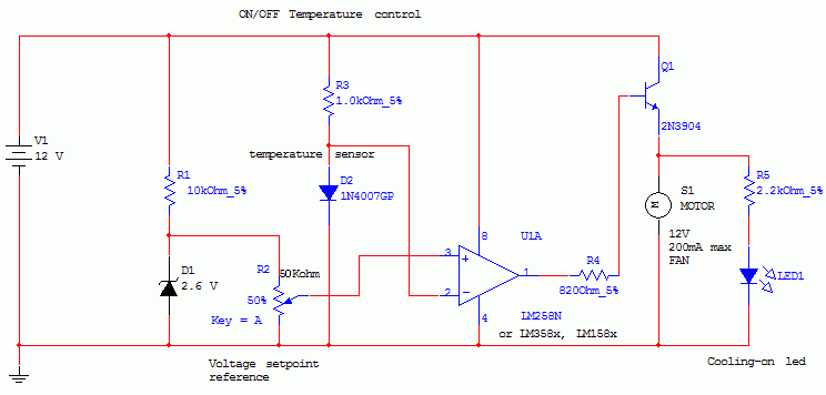
This circuit controls a load, specifically a DC brushless fan, based on a temperature comparison with a setpoint. The transducer utilized is a diode in the forward bias configuration. When forward biased, the forward voltage drop across the diode...
The circuit employs two Light Dependent Resistors (LDRs) arranged in series with a separation of approximately half a meter. This configuration allows each LDR to detect the presence of a person entering or exiting the room. The processed outputs...