
FM IF amplifier circuit composed of ceramic filters
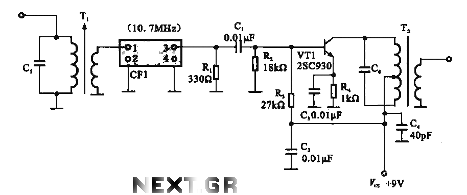
The FM IF amplifier circuit operates by receiving an intermediate frequency signal at 10.7 MHz, which is a standard frequency for FM radio systems. The circuit begins with the input signal being fed into the primary winding of transformer T1, which is configured as part of a resonant circuit. This configuration allows for selective amplification of the desired frequency while attenuating others, ensuring that only the relevant signal is processed.
The ceramic filter CF1 plays a crucial role in this setup by providing a narrow bandwidth around the 10.7 MHz frequency. This filter is essential for maintaining signal integrity, as it reduces interference from adjacent channels and enhances the overall quality of the received signal. The output of the ceramic filter is then connected to the base of transistor VT1, which serves as the main amplification stage of the circuit. Transistor VT1 amplifies the selected intermediate frequency signal, increasing its amplitude for further processing.
Following amplification, the signal is passed to the secondary transformer T2, which further conditions the signal before it is sent to the next stage of the FM receiver. The use of transformers in this circuit helps in impedance matching and allows for efficient signal transfer between stages.
Overall, this circuit exemplifies a straightforward yet effective approach to FM signal amplification, leveraging ceramic filters and transformers to achieve high performance in radio frequency applications. The design considerations prioritize simplicity and reliability, making it suitable for various FM receiver implementations.It shows a ceramic filter composed of FM IF amplifier circuit, the FM intermediate frequency amplifier circuit mainly by the IF input variable voltage regulator T}, ceramic filters CF1, IF amplifier and IF transformer T2 VT1 other parts can normally be used amplifying FM IF signal. IF from the FM front-end circuitry (10.7 MHz) into the first intermediate frequency signal TJ transformer primary winding which cs composition and frequency of the resonant circuit, having a frequency selection function, Tl transformer secondary connected with a 10.7 MHz ceramic filters it will send the selected intermediate frequency signal to an intermediate frequency amplifier at the base of the transistor VT1, amplified. VT1 amplified signal and then by the second intermediate frequency transformer Tz output to the next level.
The circuit has a simple structure, good performance characteristics.
Related Circuits
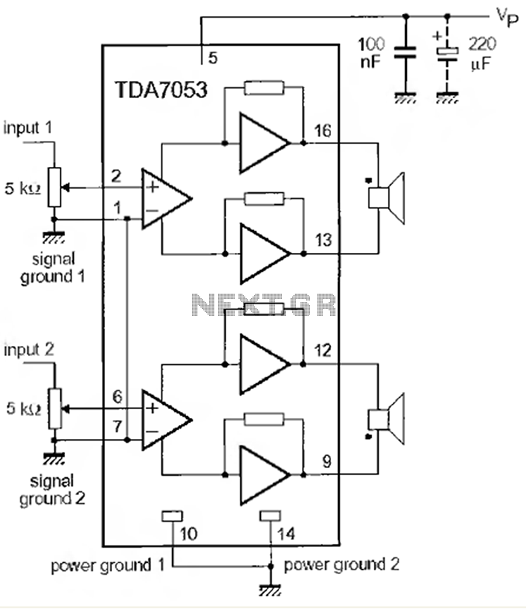
This is a 1-watt stereo audio amplifier circuit utilizing the TDA 7053 integrated circuit from Philips. It is specifically designed for battery operation, delivering 1 watt per channel from a 6V DC supply. The circuit operates optimally between 6V...
The amplifier drives a pair of loudspeakers using two LM3876 integrated power amp ICs (50 watts per channel), or a pair of headphones via a Meier crossfeed filter and an OPA2134 dual opamp. It provides four switchable line level...
As readers may know, there are several power amplifier projects, including two that utilize integrated circuit (IC) power amplifiers, commonly referred to as power op-amps. Both of these projects have gained popularity, and this new project is not intended...
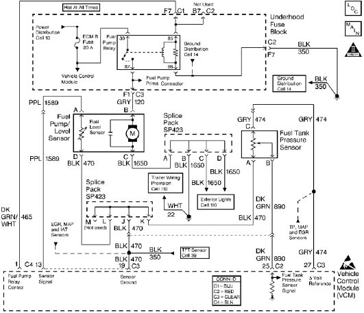
The control module monitors the fuel tank pressure (FTP) sensor signal to detect vacuum decay and excess vacuum during the enhanced evaporative emission (EVAP) diagnostic. The Fuel Tank Pressure Sensor responds to changes in the fuel tank pressure or...
This is an audio power amplifier that delivers 40 W at 8 ohms in Class A operation. The power transistors are continuously active, enabling a substantial current to flow. The audio power amplifier described operates in Class A mode, which...
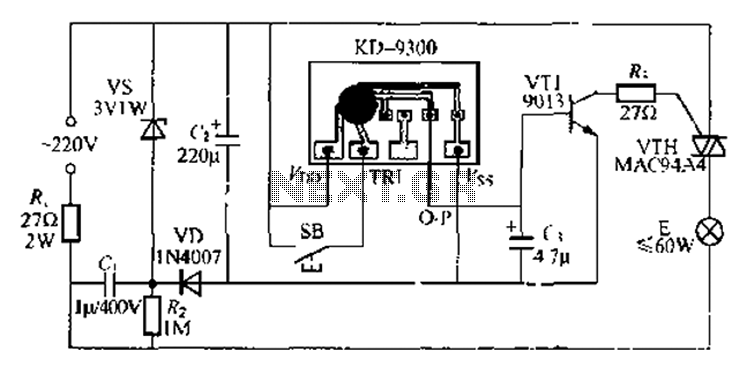
The circuit utilizes a KD-9300 music IC, which activates when the button switch (SB) is pressed, causing the electric lamp (E) to light up for approximately 20 seconds before automatically turning off. The setup includes a half-wave rectifier and...
Warning: include(partials/cookie-banner.php): Failed to open stream: Permission denied in /var/www/html/nextgr/view-circuit.php on line 713
Warning: include(): Failed opening 'partials/cookie-banner.php' for inclusion (include_path='.:/usr/share/php') in /var/www/html/nextgr/view-circuit.php on line 713