
RF drive audio oscillator
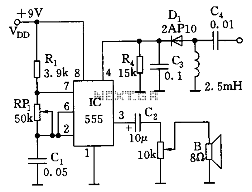
The described circuit utilizes the 555 timer in astable mode, which enables it to generate a continuous square wave output. The frequency of the oscillation is primarily influenced by the resistive and capacitive components connected to the timer. Resistor R1 is connected in series with the variable resistor RP1, which provides the ability to adjust the resistance and consequently the frequency of the output signal. The capacitor C1 is connected in parallel with the resistors and plays a critical role in determining the timing intervals of the oscillation.
In practical applications, the frequency range of 600 Hz to 20 kHz is suitable for various audio signal generation purposes, including tone generation, sound synthesis, and modulation applications. The ability to adjust RP1 allows for fine-tuning of the output frequency, making the circuit versatile for different audio applications.
The circuit can be implemented on a breadboard or a printed circuit board (PCB) for stability and durability. It is essential to ensure that the power supply voltage is within the operating range of the 555 timer, typically between 4.5V to 15V, to ensure reliable operation. Additionally, proper bypass capacitors should be included to filter any noise from the power supply, enhancing the performance of the oscillator.
Overall, this 555 timer-based audio oscillator circuit is a fundamental design that serves as an excellent introduction to oscillator design and audio signal processing, with numerous applications in electronic projects and sound-related endeavors.As illustrated, 555 and Rl, RPl, C1 controllable audio oscillator and other components, f 1.44/(R1 + 2RP1) C1, the parameters shown in the frequency between 600Hz ~ 20kHz, can be adjusted RP1 selected.
Related Circuits
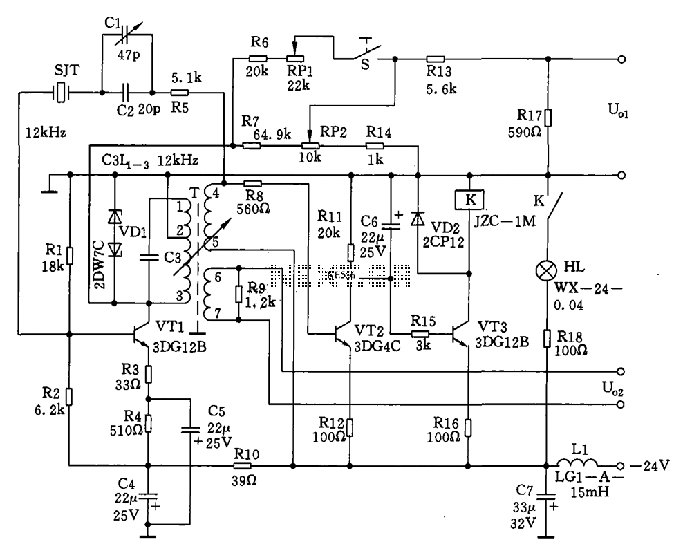
The circuit features a 12kHz intermediate frequency (IF) oscillator utilizing a quartz crystal for precision frequency generation. It includes components for output level adjustment, a level-up circuit, and an alarm circuit. The design employs a unique single-tuned variable feedback...
These motors consist of two coils and are operated by altering the direction of current flow through the coils in a specific sequence. They feature only four wires and cannot be directly connected to this kit. Refer to Kit...
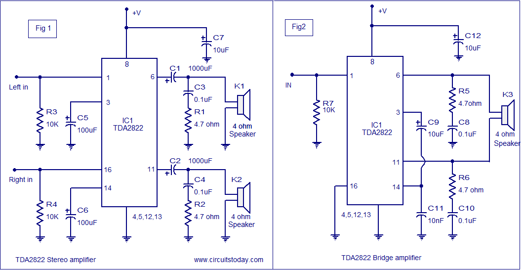
The TDA2822 audio amplifier circuit provides 1.35W output into a 4-ohm speaker when powered by a 6V supply. It supports both bridge and stereo modes and operates within a supply voltage range of 3V to 15V, making it suitable...
An input sine wave applied to the left amplifier base results in the collector output fluctuating above or below 6.6 volts. The amplifier amplifies and inverts the signal, maintaining a roughly centered output, thereby minimizing the chances of clipping....
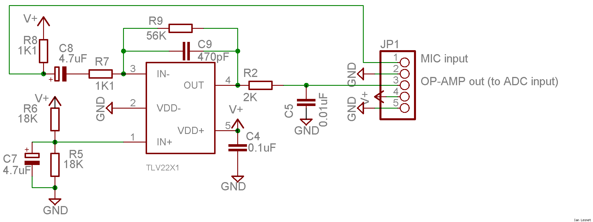
This project utilizes a small, common electret microphone to convert audio into an electrical signal. These inexpensive microphones are typically found in most PC headsets. The output from the microphone must be amplified and zeroed before it can be...
Class D amplifiers are significantly more efficient than traditional amplifiers; however, this high efficiency is accompanied by increased noise and distortion. The frequency and time-domain characteristics of a Class D amplifier, including its output filter, can be evaluated using...
Warning: include(partials/cookie-banner.php): Failed to open stream: Permission denied in /var/www/html/nextgr/view-circuit.php on line 713
Warning: include(): Failed opening 'partials/cookie-banner.php' for inclusion (include_path='.:/usr/share/php') in /var/www/html/nextgr/view-circuit.php on line 713