
Power Amplifiers Audio Circuits
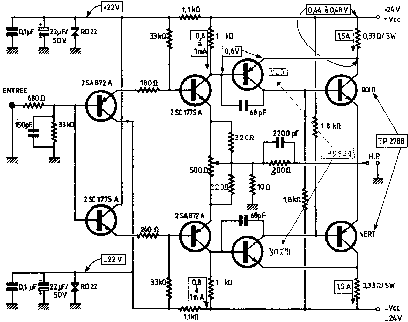
Class D amplifiers utilize pulse-width modulation (PWM) to achieve high efficiency, where the output transistors operate in saturation or cut-off states, minimizing heat generation. This design allows for compact implementations suitable for portable devices and high-power applications. The digital amplifier discussed operates on a 13.5-Volt supply and can produce 20W per channel, making it suitable for a range of audio applications, including home theater systems and portable speakers.
The Linkwitz transform circuit enhances the performance of subwoofers by allowing adjustments to the frequency response, enabling a flat output across a wide range of frequencies. This flexibility is particularly beneficial in sealed enclosures, where the acoustic characteristics can be fine-tuned for optimal sound reproduction. The parameters of the transform circuit, such as the cutoff frequency and gain, can be adjusted to suit various speaker designs and enclosure sizes.
The active crossover network plays a crucial role in audio systems by dividing the audio signal into different frequency bands, directing low frequencies to the subwoofer while sending mid and high frequencies to other speakers. This separation ensures that each speaker operates within its optimal frequency range, enhancing overall sound quality and preventing distortion.
For designers, the availability of a spreadsheet calculator facilitates the selection of appropriate component values, allowing for customization of the circuit to meet specific design requirements. This tool can assist in optimizing the performance of the amplifier and equalization circuit, ensuring that the final audio output meets the desired specifications.Class D amplifiers are much more efficient than other Classical amplifiers, but their high efficiency comes at the expense of increased noise and distortion. You can assess the frequency- and Time-domain characteristics of a Class D amplifier, including the output filter, using online simulations.
Class T Digital Audio Amplifier Evaluation Board This application note describes a digital amplifier, which operates from13. 5-Volt power source and outputs up to20W poor channel power. The application note is in PDF format. Uses a Digital Power Processing Technology EB TA2020 from Tripath Technology. Subwoofer Equalizer : The Linkwitz transform circuit is a hugely flexible way to equalize the bottom end of a sealed loudspeaker enclosure. A speaker that is corrected using this method is flat from below resonance to the upper limit of the selected driver.
The low frequency roll off point is determined by the parameters of the transform circuit. Should the enclosure size be too small and cause a lump in the response before roll off, this is also corrected. A conventional active crossover network is then used to divide the subwoofer signal from the main channel signals.
Note that there is also a separate spreadsheet calculator available for calculating component values for different situations not handled by the original circuit. 🔗 External reference
Related Circuits
It is widely recognized that any closed-loop system has a unit gain in the noise temperature ratio. The phase shift within such a system varies with frequency, and at a phase shift of 360 degrees, stability in the closed-loop...
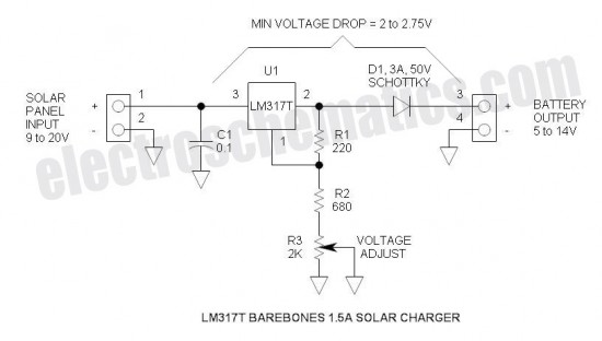
This is a simple and cost-effective solar battery charger that can be constructed by hobbyists. It has some limitations compared to other similar controllers, but it also provides several benefits. While primarily designed for charging lead-acid batteries, it can...
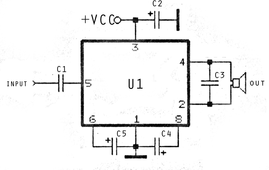
The image above depicts a miniature audio amplifier that is quite simple in design. A schematic for this audio amplifier is provided, which requires only a few components, as detailed in the accompanying diagram. This amplifier is inexpensive to...
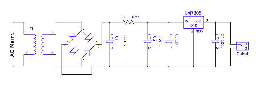
A regulated 5-volt DC supply is essential for powering microcontroller and TTL-based circuits. The output of most wall adapters is often too rippled and impure for use in digital circuits. An inexpensive power supply can be constructed using discrete...
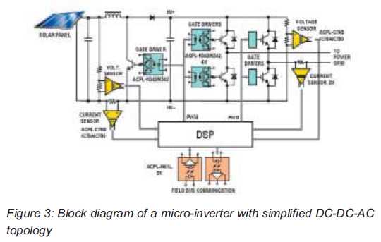
Both help improve efficiency and protect micro-inverters in photovoltaic (PV) solar applications. In 2009, the residential solar photovoltaic (PV) inverter market represented 90 percent of the total PV. The integration of micro-inverters in photovoltaic solar applications has significantly enhanced system...
On occasions when it is necessary to determine if an amplifier is functioning, the most effective tool is an acoustic signal source with a frequency around 1 kHz. The specifications can be considered flexible, as rapid tests typically do...
Warning: include(partials/cookie-banner.php): Failed to open stream: Permission denied in /var/www/html/nextgr/view-circuit.php on line 713
Warning: include(): Failed opening 'partials/cookie-banner.php' for inclusion (include_path='.:/usr/share/php') in /var/www/html/nextgr/view-circuit.php on line 713