
Capacitive switch circuit diagram
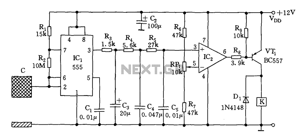
The circuit described functions as a proximity switch utilizing capacitive sensing to detect the presence of a nearby object, typically a human body. The primary components include a capacitive oscillator, which generates an oscillating signal based on the capacitance changes induced by nearby conductive objects. The 555 timer, configured in astable mode, serves as the core oscillator, producing a square wave output that varies in frequency depending on the capacitance detected.
The integration network processes the output from the 555 timer, shaping the signal to ensure that it is suitable for comparison. The LM324 operational amplifier acts as a comparator, comparing the oscillation frequency against a predefined reference voltage. When the capacitive effect from the object alters the frequency beyond a certain threshold, the comparator outputs a negative pulse.
This negative pulse is crucial as it triggers the transistor VT1, which in turn activates the relay (K). The relay serves as a switch for the load circuit, allowing it to be turned on when the object is detected and turned off when it is removed. The design ensures that the relay is deactivated when the proximity condition is no longer met, effectively controlling the load based on the presence of the detected object.
The selection of the induction plate size is critical for the performance of the circuit. It must be designed to operate at frequencies in the range of several kilohertz to ensure reliable operation. A larger plate may increase sensitivity, while a smaller one may lead to reduced detection range and reliability. Overall, this circuit is an effective solution for applications requiring non-contact switching based on proximity detection.As illustrated, the switch circuit by capacitive oscillator, the integration network, and a comparator circuit relay control circuit. When the body close to the induction metal plate, inductive capacitance to ground increases, the composition of the 555 astable multivibrator start-up or change in the oscillation frequency, alternating square wave output of the network after the three points, added to IC2 (LM324) with the phase of the comparator, and the set reference voltage, and outputs a negative pulse jump change, VT1 conduction, K pull, load circuit switched on. Conversely, disconnected. Induction plate size selection, should not be lower than the oscillation frequency of several thousand kHz.
Related Circuits
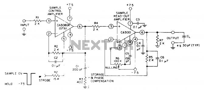
The circuit utilizes a CA3130 BiMOS operational amplifier as the sample-readout amplifier for the storage capacitor C1, while a CA3080A serves as the sample-control amplifier. Applications in linear systems that temporarily store analog data encompass digital voltmeter (DVM) systems,...
Diodes and thyristors have limited tolerance to over-current and over-voltage conditions. Short-term exposure to excessive voltage or current can damage these components and prevent them from achieving their full potential. The parameters of these devices should be determined based...
This is a follow-up to an earlier post regarding a specific circuit schematic. The circuit is designed to operate at a supply voltage of 5V, and testing has confirmed that the original device functions correctly at this voltage. A...
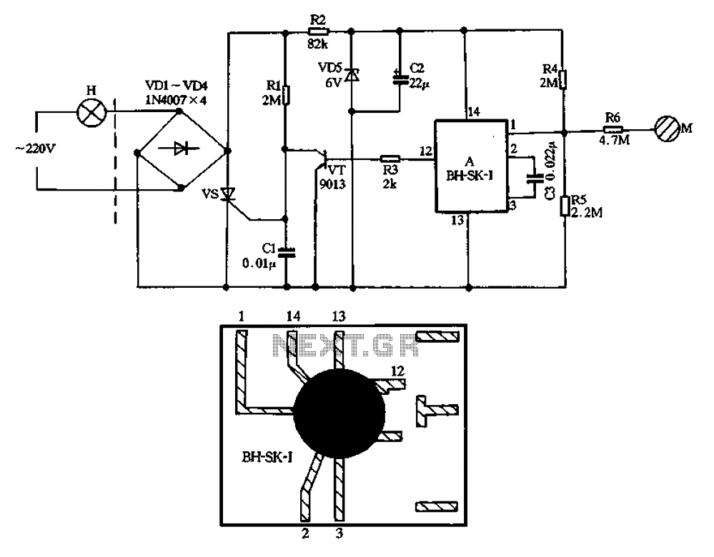
The BH-SK-I is a touch light switch circuit that integrates a single bond voice integrated circuit. The circuit is divided into two sections: the left section represents the general lighting lines, while the right section illustrates the touch switch....
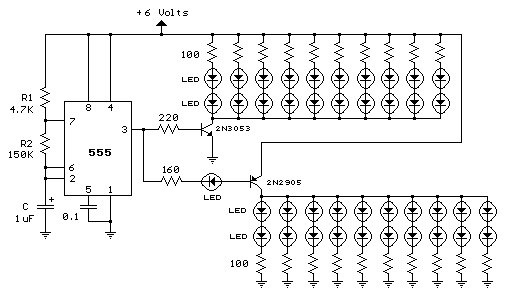
This LED series will blink alternately. The operation is determined by the NE555 integrated circuit, with transistors used to reinforce each section (20 upper, 20 lower) for optimal performance. The 555 circuit described below functions as a flashing bicycle...

The schematic for the board is illustrated below. The three primary components of the board include (1) the power input and voltage regulation, (2) the L297 input and outputs, and (3) the L298 stepper motor control circuit. The motor...
Warning: include(partials/cookie-banner.php): Failed to open stream: Permission denied in /var/www/html/nextgr/view-circuit.php on line 713
Warning: include(): Failed opening 'partials/cookie-banner.php' for inclusion (include_path='.:/usr/share/php') in /var/www/html/nextgr/view-circuit.php on line 713