
infrared Help Troubleshooting This Circuit
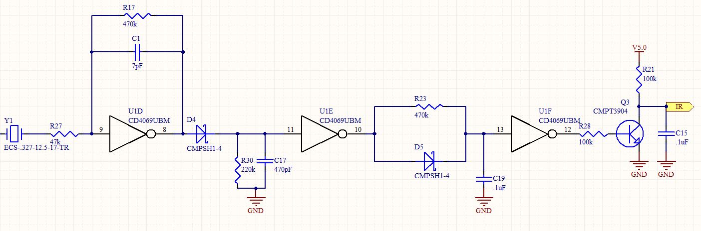
The circuit configuration involves a series of inverter stages leading to the U1E component, which is critical for determining the output states based on the input signals. The observed behavior at the input of U1E suggests that the circuit's sensitivity to IR signals may be affected by the voltage supply levels, particularly around the 3.6V threshold. The oscillation noted at pin 8 of U1D could indicate a potential instability in the circuit design, possibly due to insufficient biasing or grounding issues.
To address the problem, it may be beneficial to implement a biasing network at the input of U1E. This could involve the addition of resistive components to establish a stable reference point, enhancing the circuit's ability to discern between high and low states in the presence of minimal IR signals. Additionally, ensuring proper decoupling and filtering around U1D might help mitigate the unintended oscillations observed. It is also recommended to review the layout for any potential parasitic capacitance or inductance that could be influencing the circuit's performance, especially at higher supply voltages.
Further testing and refinement of the PCB may be necessary to achieve consistent performance across the intended operating voltage range. Implementing these modifications should improve the reliability of the circuit while eliminating the reliance on temporary solutions such as the wire attached to pin 8.This is a follow up to an earlier post I made here. Below is the relevant portion of the schematic for this issue (stuff to the left of Y1 is in original post if necessary). I have finally gotten this circuit working somewhat reliably with one exception. The original device (read layout) is intended to work at 5V. I have the original device and c an verify that it does work properly at 5V. I just got my PCB back which has a copy of the circuit. I populated the board and fired it up and it seemed to work like a champ. I had both (original and copy) wired up on the bench and was looking at the output of each channel on the scope. Things looked great. Then, I happened to notice that I was powering up the two from 3. 3V as I`ve been switching between projects and did not change the power supply voltage when I last switched.
I begin to adjust the voltage up toward 5. 0V and I notice that right about 3. 8V the output of the copy goes low and stays low up to 5. 0V. I lower the voltage and it goes high (but toggles low when IR present) at about 3. 6V. So, the circuit works at a supply voltage < ~ 3. 6 V. With the voltage set at 5. 0V I start to probe around comparing all signals to the original. Following the individual inverter stages things look identical right up to the input of U1E (pin 11). As I vary the voltage across that threshold of roughly 3. 6V that pin toggles. So, next I want to take a look at the output of U1D (pin 8). I found it quite difficult to probe this and watch the scope at the same time as the probe would slip off the contact point.
So, I decided to take a piece of 3" wire wrap and tack it onto the pin so that I could grab a hold of it with the probe. I did that, fired it up and the circuit behaves quite nicely! It operates as expected. At this point I don`t even have the probe on the wire I tacked onto the pin. So, the addition of this wire hanging from the pin has solved my issue. The blue trace is the output of the entire circuit (Q3 Collector). The magenta trace is the input of U1E (or cathode of D4). You`ll notice I gave each two pulses from the transmitter. In the snapshot without the wire tacked you`ll notice that the steady state is quite noisy. Of course, hanging a wire off this pin is not a real solution and I don`t understand why it works so that is the reason for my question.
What should I do here Just thinking out loud that it would be nice if I could fix a `bias point` on the input of U1E so that minimal IR receive is necessary for a high. There seems to be a 32. 768 kHz oscillation at U1D (pin 8) with no IR signal present. This oscillation kicks in when the supply voltage is roughly 3. 1V. By 3. 6V to 3. 8V it is prevalent enough to cause the output of U1E (pin 10) to drive low. 🔗 External reference
Related Circuits

This simple circuit can be used to sense the distance between the rear bumper of a car and any obstacle behind it. The distance is indicated by the combination of LEDs (D5 to D7) that illuminate: at 25 cm,...
This sound effects circuit is designed to function as a signal distorter. When utilized with an electric guitar, it enables the creation of unique sound effects. The sound effects circuit operates by manipulating the input audio signal from the electric...
LM1036 Stereo Tone (Bass, Treble, Volume, Loudness, Balance) Controller Circuit. The LM1036 is a DC controlled tone (bass/treble), volume, and loudness controller designed for audio applications. The LM1036 circuit serves as an integrated solution for controlling various aspects of audio...
This is a simple game show timer designed for beginners. The power source can be a standard 12-volt lantern battery or a battery pack made from C or D cells. The lamps used can be regular flashlight bulbs; the...
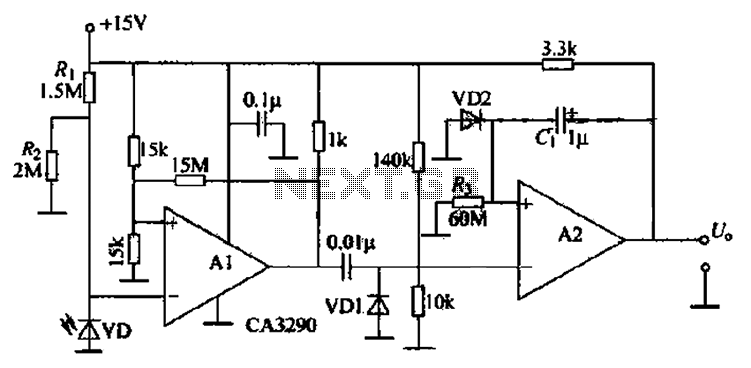
The circuit includes comparators A1 and A2, which function as a single-trigger timing device. When the light is interrupted, the current through photodiode VD changes. The output of A1 triggers A2, causing A2's output to go low and remain...
The timing doorbell circuit utilizing the CW9300 is depicted in the provided diagram. This circuit features a timing function that, upon pressing the button, plays music for a specified duration. If the button is pressed again immediately after releasing...
Warning: include(partials/cookie-banner.php): Failed to open stream: Permission denied in /var/www/html/nextgr/view-circuit.php on line 713
Warning: include(): Failed opening 'partials/cookie-banner.php' for inclusion (include_path='.:/usr/share/php') in /var/www/html/nextgr/view-circuit.php on line 713