
By BH-SK-1 produced a single bond Touch light switch

The BH-SK-I touch light switch circuit is designed to provide a seamless transition from traditional mechanical switches to a modern touch-sensitive interface. The integration of a voice IC allows for enhanced functionality, enabling users to control lighting with simple touch gestures. The circuit architecture employs a combination of SCRs and diodes to create a reliable control mechanism, ensuring that the lamp operates efficiently under varying conditions.
The voltage regulator formed by R2, C2, and VD5 ensures that the circuit receives a stable 6V DC supply, which is critical for the performance of the voice IC. The voltage divider created by R4 and R5 is essential for setting the bias voltage at the input pin, allowing for sensitivity adjustments that can cater to different environments and user preferences.
The bistable operation of the voice IC is a key feature that allows for intuitive control of the lamp. The output from pin 12 directly influences the state of the transistor VT, which acts as a switch for the lamp. The ability to toggle the state of the lamp with a simple touch on electrode sheet M provides a user-friendly experience, while the internal processing of the noise signal ensures that accidental touches do not lead to unintended operation.
In terms of power management, the circuit's CMOS design is advantageous, as it minimizes power consumption while maintaining operational integrity. The voltage drop across capacitor C2 during lamp operation indicates that the circuit can sustain itself even with reduced power levels, making it suitable for applications where energy efficiency is a priority.
Overall, the BH-SK-I touch light switch circuit exemplifies a modern approach to lighting control, combining ease of use with advanced electronic components to deliver a reliable and efficient solution for both residential and commercial applications. BH-SK-I with the voice of a single bond integrated circuit fabrication touch light switch circuit shown in Figure, the dashed line in Figure 3-40 left section for the general l ighting lines, the right part is the touch switch. Be seen by its ordinary mechanical switches, Foreign cited only two stages, so you can easily replace the ordinary switch without changing the original interior wiring. Switch back to the main route SCR vs diode VD1 ~ VD4 and composition, voice integrated circuits control loop.
R2, and C2 form VD5 simple regulator circuit, for the manifold provides 6V DC voltage, resistors R4, R5 partial pressure of the composition is for the manifold l input pin provides slightly. 1/2 VDD bias voltage, so that the manifold in a more sensitive state. SCR vs turned on or not, depending on the switching state of the transistor VT. When the VT is off state, vs through resistor R1 and the opening of the current administration to obtain contact, namely H lamp is lit; when the VT in the conduction state.
VT vs gate is shorted to ground. vs in the off state, the lamp goes out. Won voice IC is in a bistable operation mode, its output level is 12 feet high low determines the lamp is lit or extinguished. If the 12-pin output high, VT conduction, vs off, the lights go out. Turn on the lights when needed, as long as your fingers touch the electrode sheet M. Human induced noise signal is applied to the manifold via a resistor R6 to the input end of the l foot, after the internal manifold circuit processing, the internal flip-flop flip, 12-pin output low, so transistor VT CD stop, vs open, lights on the point H shell.
Such as touching a lower electrode sheet M, the manifold internal bistable trigger fork flipping once, 12 feet high output, VT conduction, vs off, the lamp H goes out. Therefore, by hand contact electrodes M, you can turn on and off operation. In vs opened, when the lamp is lit, C2 both ends of the voltage will drop to around 3V, because the BH-SK- I belong CMOS circuit power consumption is minimal, it can still maintain normal work, so do not worry about it.
Related Circuits
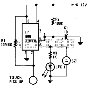
The circuit is based on a 555 oscillator (U1), which activates when a trigger is applied by touching the touch terminal connected to pin 2 of U1. Once triggered, LED1 and BZ1 (a piezoelectric buzzer) illuminate for a duration...
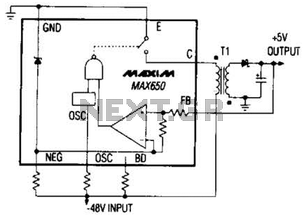
The Max650 switching regulator generates a regulated 5 V output from large negative voltages, such as the -48 V commonly found on telephone lines. This power supply requires several external components, including a transformer, and is capable of delivering...
The Saver V5.0 runs simple clock emulation program, turns a night light on and off with preset time, say 19:00 to 22:00 everyday. The design features low cost, easy installation, no battery backup and no EMI. The AT89C2051 uses...

This sound-operated switch detects the ringing of a phone and activates a lamp accordingly. The amplified signal across resistor R2 reaches diode D1 through capacitor C2. The rectified audio signals create a negative bias for transistor Q2, a PNP...
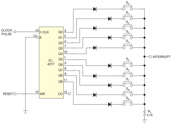
There are several methods to read multiple switch inputs using a reduced number of microcontroller unit (MCU) pins. One approach involves using an analog MCU pin to read multiple switches by assigning a unique voltage to each switch through...
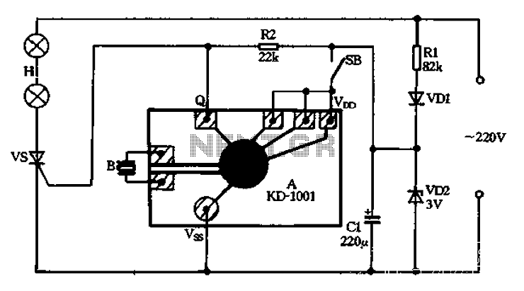
A 220V AC power supply is utilized through a resistor R1 to step down the voltage, followed by a rectifier VD1 and a filter capacitor C1, resulting in an output voltage of approximately 3V DC for the KD-1001 manifold....