
Dual flashing string circuit 2

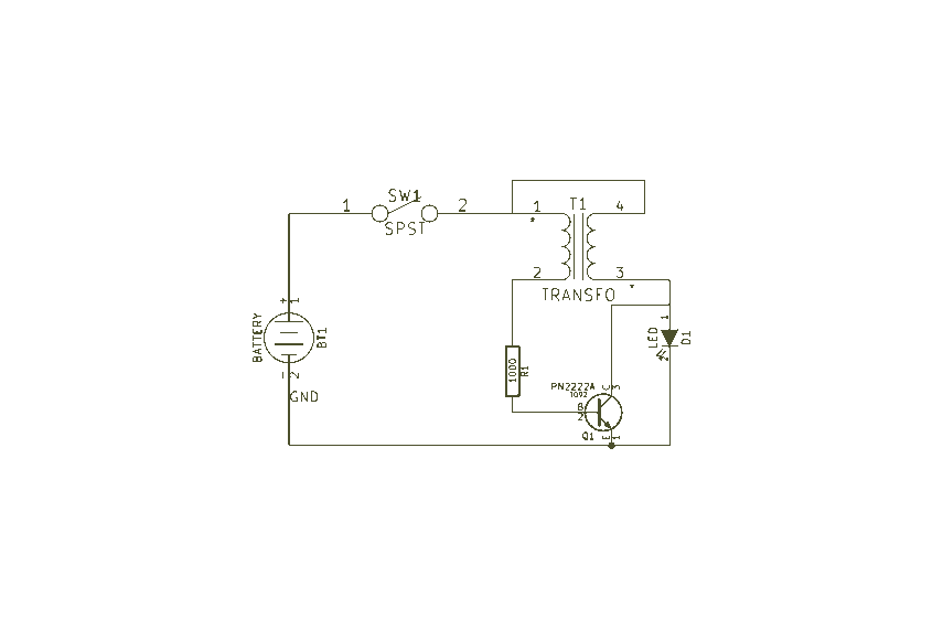
The thyristor-controlled unidirectional flashing light string controller is designed to manage the operation of two separate light strings, E1 and E2, in an alternating manner. The core of the circuit relies on the switching capabilities of thyristors VT3 and VF4, which are triggered by the activation states of transistors VT1 and VT2. The multi-oscillator circuit provides the necessary timing signals to ensure that VT1 and VT2 operate in a complementary fashion, allowing one to turn off while the other turns on.
The resistors R1 and R2 serve as current limiting and biasing components, ensuring that the thyristors receive the appropriate gate trigger currents. The use of diodes VT1 and VT2 helps prevent backflow of current, ensuring that each thyristor operates effectively within its specified parameters. The LED indicators I1 and I2 not only provide visual feedback on the operational status of the light strings but also serve as a diagnostic tool for troubleshooting the circuit.
The multivibrator section of the circuit is crucial for establishing the flashing frequency of the light strings. By adjusting the resistance in the feedback loop, the frequency of the oscillation can be modified, allowing for customization of the flashing pattern. The choice of components, including the use of standard thyristors and polypropylene capacitors, ensures reliability and ease of sourcing, making the circuit suitable for various applications in decorative lighting or signaling systems.
Overall, this thyristor-controlled flashing light circuit exemplifies an efficient and effective design for managing alternating light displays, utilizing basic electronic components to achieve a visually appealing result.As is the use of thyristor controlled unidirectional flashing lights string controller, diodes VTI, VT2 connected to a multi-I are from Che oscillator, after power, VT1, VI12 t ake turns alternately turned on and off. When VT1 is turned off when VT2 DC power supply on by R;, IFDl single injection of the thyristor VT3 door, so vn opened, El string lights lit; if VT1 end, when VT2 guide slovenly, when the light-emitting tube I. EDl off, VT3 fail to trigger current shutdown, E1 put out in particular. While DC power supply by R, I: D2 injection of one-way thyristor VF4 f J pole, so v D 4 E2 open string lights lit, so the labyrinth light strings El and F: 2 alternately flashing light and flame.
LED tube plate I. F: r) l and LFD2 play indication, representing J bright fire and light string {: l, F2 synchronous deep change section RP old white excited multivibrator oscillation frequency, it. Section can split half flashing lights. AC frequency comb. VT3, VT4 cho MCRI .- S-type and other small plastic single product BJ thyristor .f require (: 1-1H 400V polypropylene capacitors five other devices without special requirements.
Related Circuits
The recommendation regarding the existing phono connector is to maintain its current configuration without making significant alterations. The procedure involves replacing the electrolytic and paper capacitors, adding a three-wire line cord, and utilizing the radio in its original state....

This circuit is based on a Philips class-H audio amplifier integrated circuit (IC) and can deliver 36W RMS or 70W music power, all from a 13.8V supply. The Mighty Midget Amplifier is capable of providing approximately 36W RMS continuous...
Easy Joule Thief Soldering Kit from MakersBox on Tindie The Easy Joule Thief Soldering Kit is designed for educational purposes, allowing users to learn about basic electronics through hands-on experience. This kit includes all necessary components to assemble a Joule...
%2Band%2B(US)%2BCX500%2BC%2B1979-81%2Band%2B1979%2BCX500%2BD%2BElectrical%2BWiring%2BDiagram.jpg)
Lamp Electrical Circuit Diagram Manual PDF Download. This document provides a comprehensive manual for downloading the electrical circuit diagram of a lamp. The circuit diagram serves as a crucial reference for understanding the electrical connections and components involved in lamp...

This design is for a thermometer circuit that utilizes the LM35 integrated circuit (IC) as a temperature sensor. It is a straightforward circuit that allows for the measurement of room temperature using a digital voltmeter or any voltmeter capable...

This circuit illustrates a 2W RF amplifier based on the M/A-Com LF2810A MOSFET. The transistor is rated for 10 watts at 28 volts. The 2W RF amplifier circuit utilizing the M/A-Com LF2810A MOSFET is designed to amplify radio frequency signals...
Warning: include(partials/cookie-banner.php): Failed to open stream: Permission denied in /var/www/html/nextgr/view-circuit.php on line 713
Warning: include(): Failed opening 'partials/cookie-banner.php' for inclusion (include_path='.:/usr/share/php') in /var/www/html/nextgr/view-circuit.php on line 713