
fahrenheit thermometer circuit

This thermometer circuit leverages the LM35 temperature sensor, which provides an output voltage proportional to the temperature in degrees Celsius. The LM35 operates over a wide temperature range, typically from -55°C to 150°C, with a linear output of 10 mV/°C. This means that at 25°C, the output voltage will be 250 mV.
To accurately measure the voltage output from the LM35, it is essential to utilize a voltmeter with high input impedance to avoid loading effects that could distort the readings. The floating output voltage indicates that the circuit does not have a direct ground reference, which is a design consideration when connecting to measurement devices. If the voltmeter is single-ended and references ground, a separate power supply is required to avoid ground loops and ensure accurate readings.
The differential input adapter serves to convert the floating output of the LM35 into a form that can be interpreted by a single-ended voltmeter. This adapter typically includes operational amplifiers configured in a differential mode, allowing the circuit to measure the voltage difference between the output of the LM35 and a reference voltage.
The circuit can be designed with additional features, such as an adjustable gain to allow for different measurement ranges or a calibration mechanism to ensure accuracy. In practice, setting the voltmeter to the 200 mV range allows for a straightforward conversion of the measured voltage to temperature in degrees Fahrenheit, simplifying the user experience and enhancing the utility of the thermometer circuit.
Overall, this thermometer circuit design is suitable for various applications, including environmental monitoring, HVAC systems, and educational purposes, providing a reliable and easy-to-implement solution for temperature measurement.This is a design for thermometer. This is a simple circuit design. This circuit is based on temperature sensor using LM35 Ic. If you have a digital voltmeter, or any voltmeter with millivolt resolution and high input impedance, then you can use this temperature-to-voltage adapter circuit to measure room temperature. This is the figure of the circu it. Note that the voltage output of this circuit is floating, not referenced to ground. You have to use separate supply if your voltmeter has single ended (referenced to ground) input. Differential input adapter described here is suitable to give a differential input for your single ended meter, remember that the input impedance must be high. You can set your voltmeter to 200 mV range to give temperature reading directly in Fahrenheit degree.
🔗 External reference
Related Circuits

This circuit is designed as a 10-channel LED sequencer with the addition of solid-state relays for controlling AC lamps. The circuit operates using relays. The relay depicted in the diagram is a Radio Shack 3 amp unit (part no....
This is a solar tracking circuit designed to harness power from sunlight. The circuit operates optimally by maximizing sunlight exposure to generate electricity. The solar tracking circuit utilizes a combination of photovoltaic (PV) cells, sensors, and a microcontroller to adjust...
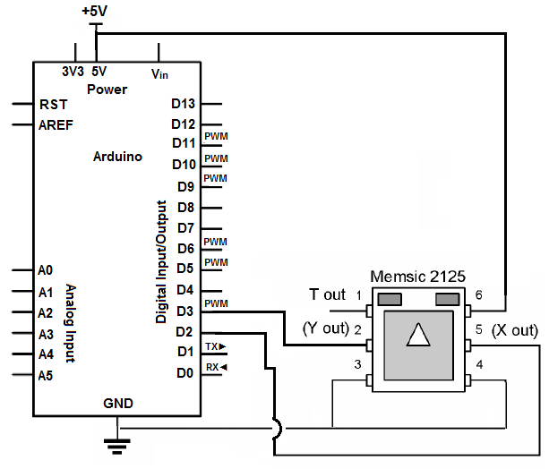
An accelerometer is a device that measures both dynamic acceleration (vibrations) and static acceleration (gravity). It can detect tilts, rotations, and movements or lack thereof, making it useful for alarm system sensing. The accelerometer can determine if it is...
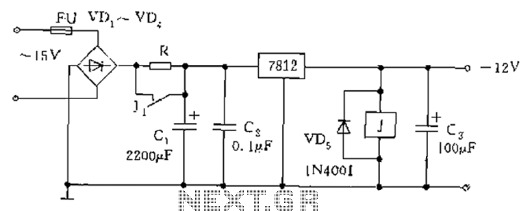
The figure below illustrates the use of a relay in the starting circuit. The power input connects through a resistor R, which serves two purposes: first, it prevents a large current from the capacitor C1 from affecting the power...

An electronic calculator features an automatic counting interface circuit, as illustrated in the accompanying figures. Figure (a) depicts a stroke switch controlled via optocoupler B. Figure (b) shows the application of a reed switch (KR) for pulse control signals....
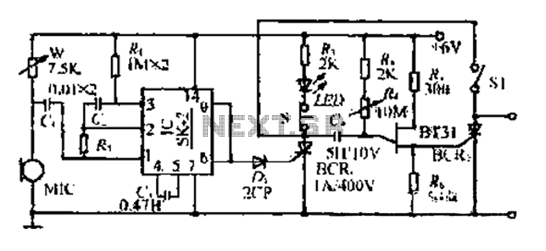
The circuit includes a microphone (MIC) housed in a cylindrical body that captures sound when an object makes contact. The audio signal is coupled to an integrated circuit (IC) for amplification. The output from the IC, at pins 6...
Warning: include(partials/cookie-banner.php): Failed to open stream: Permission denied in /var/www/html/nextgr/view-circuit.php on line 713
Warning: include(): Failed opening 'partials/cookie-banner.php' for inclusion (include_path='.:/usr/share/php') in /var/www/html/nextgr/view-circuit.php on line 713