
Relay type starting circuit diagram
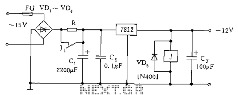
The schematic involves a starting circuit that employs a relay to manage power supply activation. The circuit includes a power input connected to a resistor R, which plays a critical role in controlling the inrush current during startup. This inrush current is primarily influenced by the charging behavior of capacitor C1. The resistor R is strategically placed to mitigate the impact of high initial currents, thus protecting the power supply from potential damage.
In the initial phase of operation, when the circuit is powered, capacitor C1 begins to charge. The resistor R ensures that this charging process does not draw excessive current, which could lead to instability in the power supply. This is essential for maintaining the integrity of the power source during the brief startup period.
The relay J is designed to engage at a specific voltage threshold below 12V. When the circuit is powered, and the voltage is within this range, the relay activates, allowing the load to receive power temporarily. The operation of the relay is crucial, as it creates a path that bypasses resistor R once the capacitors C1 and C3 are sufficiently charged. This transition allows the circuit to enter a stable operating state, where the power supply can function without the constraints imposed by resistor R.
As capacitors C1 and C3 charge, the voltage across them increases, eventually reaching a level that allows the relay contacts to close, effectively short-circuiting the resistor R. This action not only stabilizes the circuit but also enhances the efficiency of the power delivery to the load. The design ensures that the system can handle the initial surge of current while transitioning smoothly to normal operation, thereby optimizing performance and reliability in the overall circuit function. As shown below, the following figure is the use of a relay or the like of the starting circuit. Power input access resistance R, R role there are two, one: to prevent boot when the impact of current large capacitor C1 affect the power supply itself; Second: Power-up the load eligible for a few seconds. In this process, due to the output of the relay J pull-in voltage of less than 12, from limiting the role of blood pressure combined R access to the circuit, with the power to C1, C3 is fully charged, the relay J pull short-circuit the contacts R, then, before the power supply into the normal working condition.
Related Circuits
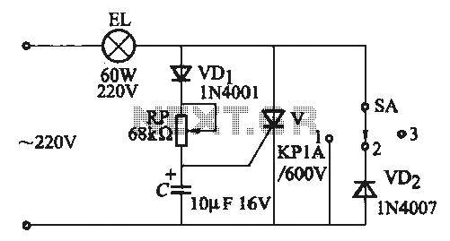
A thyristor-based incandescent dimming circuit is illustrated in Figure 2-66. Figure 2-66 (a) depicts a thyristor half-wave controlled dimmer combined with a diode approach. When switch SA is set to position "3," the adjustment potentiometer RP allows the voltage...
The industrial fuel oil furnace controller circuit consists of a power supply circuit, a testing and ignition control circuit, and a control implementation circuit, as illustrated in the accompanying diagram. The power supply circuit includes a step-down capacitor (C6),...
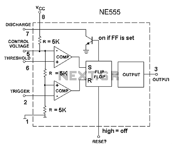
The 555 timer circuit, regardless of the manufacturer, has a consistent internal structure and performance. Various manufacturers produce different models of the 555 timer, including MC555, CA555, XR555, LM555, as well as domestic models like SL555, FX555, and 5G1555....
This caller ID circuit utilizes the Motorola MG145447 IC chip. The service must be available from your local phone company for this circuit to function properly. The caller ID circuit based on the Motorola MG145447 IC chip is designed to...
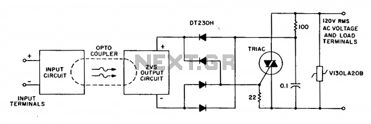
A complete zero-voltage switch solid-state relay consists of an input circuit, an output circuit, and a power thyristor. The circuit features a triac power thyristor with a snubber circuit and GE-MOVRII Vans for transient over-voltage protection. A 22-ohm resistor...
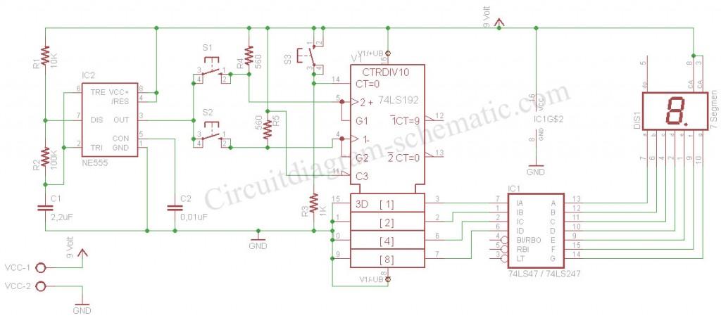
The digital scoreboard circuit is designed to display numerical values ranging from 0 to 9 on a 7-segment display. This display utilizes a common anode configuration. The digital scoreboard circuit operates by controlling a 7-segment display that utilizes a common...
Warning: include(partials/cookie-banner.php): Failed to open stream: Permission denied in /var/www/html/nextgr/view-circuit.php on line 713
Warning: include(): Failed opening 'partials/cookie-banner.php' for inclusion (include_path='.:/usr/share/php') in /var/www/html/nextgr/view-circuit.php on line 713