
Integrated solid state relay
The voltage divider responsible for sensing zero crossing must also be carefully selected to minimize power dissipation in the transistor optoisolator circuit for 220-V operation.
The zero-voltage switch solid-state relay is a critical component in various applications where precise control of AC loads is necessary. The design integrates an input circuit that typically includes a voltage divider to detect the zero crossing of the AC waveform. This detection is essential for ensuring that the power thyristor, specifically a triac in this case, is triggered at the optimal moment to minimize electrical noise and inrush current.
The output circuit comprises the power thyristor, which allows for the conduction of current when triggered. The inclusion of a snubber circuit is vital as it protects the triac from voltage spikes that can occur during switching. The GE-MOVRII Vans component serves as a transient over-voltage protector, safeguarding the circuit against voltage transients that could damage sensitive components.
The 22-ohm resistor is strategically placed to shunt di/dt currents, which are the rapid changes in current that can occur during switching events. This helps to protect the gate of the triac from excessive currents that could lead to premature failure. The 100-ohm resistor plays a critical role in limiting both surge and gate currents, ensuring that the triac operates within safe parameters.
For applications requiring 220 V operation, it is imperative to select components with appropriate voltage ratings. This includes the MOV, rectifier diodes, triac, and pilot SCR, all of which must withstand higher voltages to ensure reliable operation. The voltage divider used for zero-crossing detection must also be optimized to reduce power dissipation in the optoisolator, which is crucial for maintaining efficiency and performance in higher voltage applications.
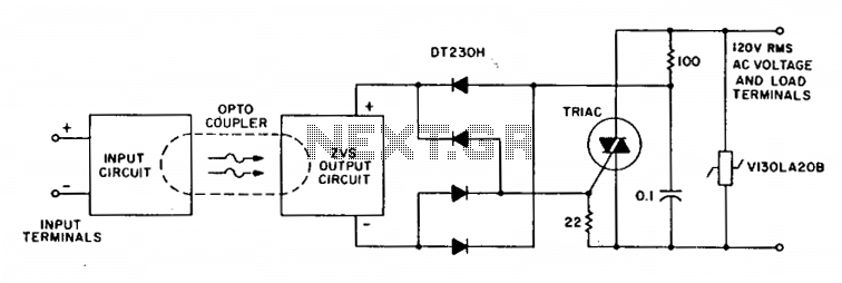
Overall, the design and components of this zero-voltage switch solid-state relay allow for effective and efficient control of AC loads, making it suitable for various industrial and commercial applications.A complete zero-voltage switch solid-state relay contains an input circuit, an output circuit, and the power thyristor. The circuit illustrates a triac power thyristor with snubber circuit and GE-MOVRII Vans tor transient over-voltage protection.
The 22 ohm resistor shunts di/dt currents, passing through the bridge diode capacitances, from the triac gate, while the 100 ohm resistor limits surge and gate currents to safe levels. Although the circuits illustrated are for 120-V rms operation, relays that operate on 220 V require higher voltage ratings on the MOV, rectifier diodes, triac, and pilot SCR.
The voltage divider that senses zero crossing must also be selected to minimize power dissipation in the transistor optisolator circuit for 220-V operation. 🔗 External reference
Related Circuits
Most Tesla coils designed for educational and experimental purposes utilize line-operated, step-up transformer setups to generate the high voltage required for the coil's primary circuit. While this approach is technically sound, it poses a risk to the operator if...
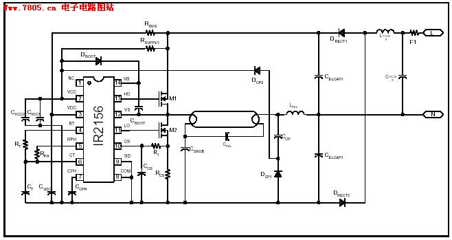
The IR2156 provides a cost-effective solution for fluorescent electronic ballasts. It integrates features such as lighting tube error protection and a programmable working frequency, which includes warm-up, lighting, and continuous operation of the ballast. The IR2156 is a highly integrated...
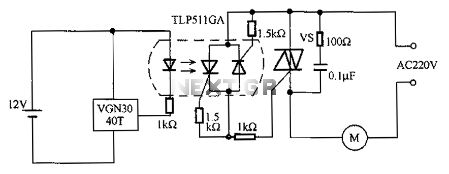
The circuit utilizes an integrated Hall effect sensor for an AC motor control system. It operates by detecting the presence of magnets or other magnetic objects near the Hall IC element of the induction motor. This configuration functions as...
A bike equipped with a 35-watt HS1 bulb is being upgraded to a brighter headlight using an H4 60/65-watt xenon bulb. An expert recommended using relays due to the increased power requirements of the new bulb. Research conducted on...
The aquarium design utilizes a DPDT relay and a 12V inverter. The selected relay is rated adequately for a 400-watt load. The 12V DC relay, transformer, and diodes consume minimal power, making efficiency a minor concern. It is unclear...
A clock-controlled relay, also known as a time delay relay, allows for the automatic activation of a load, such as a water pump, at a predetermined time. This device utilizes a standard clock mechanism to trigger the circuit, enabling...