
ISO122 124 filter circuit diagram
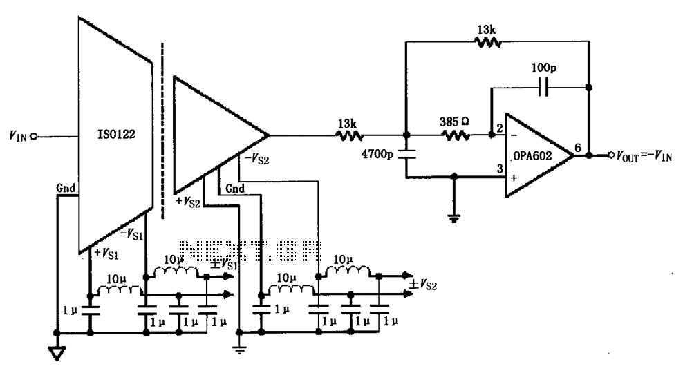
The ISO122/124 filter circuit operates by leveraging the internal oscillator frequency of 500 kHz to minimize noise interference originating from the DC/DC converter. The choice of inductors and capacitors is critical; they are selected based on their ability to effectively attenuate unwanted high-frequency components while allowing the desired signal to pass through. The filtering stage is essential for maintaining signal integrity, particularly in applications sensitive to noise.
The output from the ISO122/124 after initial filtering exhibits a ripple voltage of 20 mV at 500 kHz. This level of ripple is acceptable for many applications, but further refinement is achieved through the implementation of a two-pole low-pass filter using the OPA602 or OPA237 operational amplifiers. This configuration enhances the filtering capabilities by providing a sharper roll-off beyond the cut-off frequency of 100 kHz, thereby significantly reducing the amplitude of any remaining high-frequency noise.
The two-pole low-pass filter is characterized by its ability to attenuate frequencies above the cut-off point more effectively than a single-pole filter. This is particularly beneficial in applications where high-frequency noise can adversely affect the performance of downstream circuitry. The selection of the OPA602 or OPA237 amplifiers is based on their favorable performance characteristics, including low noise and high slew rate, making them suitable for precision filtering applications.
In summary, the ISO122/124 filter circuit is a well-engineered solution for noise suppression, combining the strengths of passive filtering elements with active components to achieve a clean output signal suitable for sensitive electronic applications. As shown by ISO122/124 -type filter circuit shown in FIG. ISO122/124 modem internal oscillator frequency is set to 500kHz, in order to suppress from the DC/DC converter is any straight (beat frequency) noise power at the end of each use filter inductor and capacitors for filtering. After filtering ISO122/124 output of 500kHz ripple is suppressed to 20mV, then cheap OPA602 (or OPA237) constitute two-pole low-pass filter further filtering, two-pole low-pass filter cut-off point of 100kHz.
Related Circuits
These accessories are low-cost, high-speed, bifet-input operational amplifiers utilizing internally compensated voltage (BI-FET II technology). They require low supply voltages while offering a wide gain bandwidth product and fast slew rate. Additionally, well-matched high voltage JFET input devices accommodate...
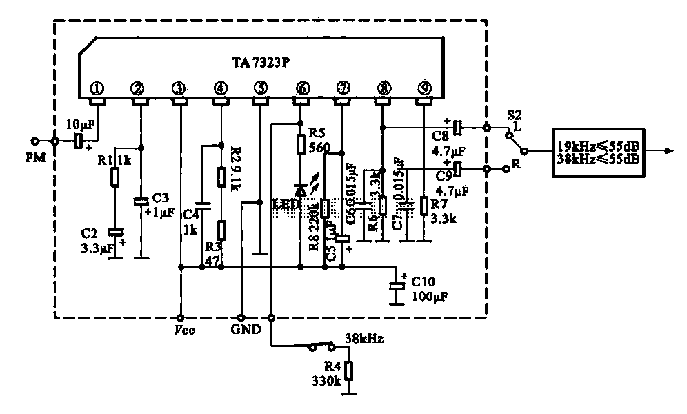
The current design utilizes a stereo decoder integrated circuit (IC) that guarantees a channel separation of 45 dB or more due to its manufacturing process. The intermediate frequency amplifier gain is sufficiently high to achieve a channel separation greater...
This circuit operates two LED strips in pulsing mode, where one LED strip transitions from an off state to gradually lighting up, then dimming, while the other LED strip performs the opposite action. Each strip can consist of 2...
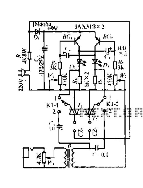
A 220V mains power supply is reduced using a control circuit designed by N. Guanidine D. Yi. The circuit features a spike Bode and provides a +9V voltage supply. It includes components such as a control port (G), a...
This schematic is provided with the intention of being useful, but it comes without any warranty, including implied warranties of merchantability or fitness for a particular purpose. The address bus in this schematic is connected in a unique manner,...
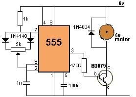
This project utilizes a 555 timer to control the speed of a 6-volt DC motor. Speed adjustment is achieved by rotating a 50 kΩ potentiometer either to the left or right. The circuit employs a 555 timer configured in astable...
Warning: include(partials/cookie-banner.php): Failed to open stream: Permission denied in /var/www/html/nextgr/view-circuit.php on line 713
Warning: include(): Failed opening 'partials/cookie-banner.php' for inclusion (include_path='.:/usr/share/php') in /var/www/html/nextgr/view-circuit.php on line 713