
dc motor control using 555 timer circuit
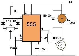
The circuit employs a 555 timer configured in astable mode to generate a pulse-width modulation (PWM) signal. This PWM signal is then used to control the average voltage supplied to the DC motor, thus regulating its speed.
The 555 timer's duty cycle can be adjusted by changing the resistance of the potentiometer, which in turn alters the width of the pulses generated. The motor is powered by a 6-volt supply, and the output from the 555 timer is fed into a transistor that acts as a switch. The transistor amplifies the PWM signal, allowing it to drive the motor effectively.
Key components of the circuit include the 555 timer IC, a 50 kΩ potentiometer, a suitable NPN transistor (such as the 2N2222), a diode for flyback protection, and the 6-volt DC motor. The diode is connected in reverse parallel with the motor to protect the circuit from voltage spikes generated when the motor is turned off.
The schematic representation of this circuit should include the connections between the 555 timer, the potentiometer, the transistor, the motor, and the power supply, ensuring that all components are properly oriented and connected to allow smooth operation. This design provides a straightforward method for controlling DC motor speed in various applications.Using this 555 timer DC motor control electronic project you can control speed of a 6 volts DC motor, by simply rotate left or right the 50 k potentiometer. 🔗 External reference
Related Circuits
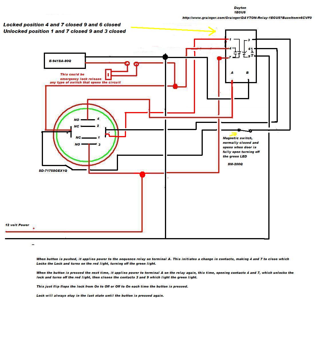
A 12V DC electromagnetic lock is designed with a push-to-lock and push-to-unlock mechanism using an existing LED indicator/switch. The switch should display a green light when unlocked and red when locked. The LED indicator/switch is the SD-7175SGEX1Q, which is...
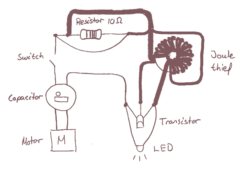
Early in the electronics design process, the decision was made to implement a joule saver in the circuit. The intention of using a joule saver is to maintain the LED light illumination even after the handle is no longer...
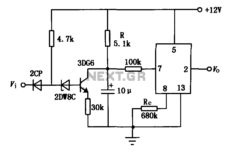
The delay application circuit is depicted in Figure JEC-2, which consists of two components. When the input transitions from logic level 0 to 1, the output also changes to 1 immediately. However, when the input transitions from high level...
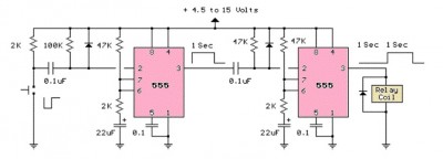
The LM555 timer circuit is similar to the previous design but incorporates two stages, allowing for control over both the pulse width and the delay. The LM555 timer is a versatile integrated circuit widely used in various timer, delay, pulse...
This simple tone control can be used in many audio applications. It can be added to amplifiers, used as a standalone control module, or even built into new and exciting instruments. Its one IC construction makes it a very...
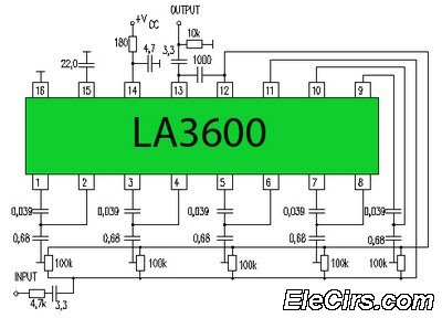
Circuit LA3600 5 Band Equalizer Circuit Schematics. One type of tone control in audio electronics is the graphic equalizer. Graphic equalizers can be categorized into two types: bar and other configurations. The LA3600 circuit is a 5-band graphic equalizer designed...
Warning: include(partials/cookie-banner.php): Failed to open stream: Permission denied in /var/www/html/nextgr/view-circuit.php on line 713
Warning: include(): Failed opening 'partials/cookie-banner.php' for inclusion (include_path='.:/usr/share/php') in /var/www/html/nextgr/view-circuit.php on line 713