
Made with hex inverter DC DC converter circuit
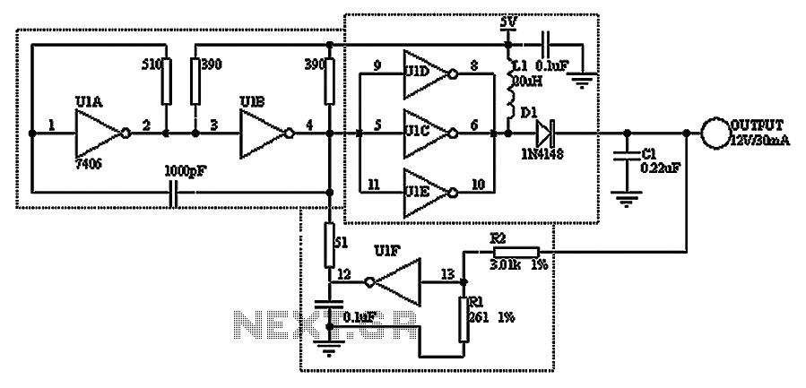
The circuit design incorporates a TTL hex inverter, which is essential for establishing the necessary voltage levels and switching characteristics for effective DC/DC conversion. The oscillator, formed by U1A and U1B, operates at a frequency of 1MHz, ensuring rapid switching necessary for efficient energy transfer. The parallel configuration of inverters U1C, U1D, and U1E enhances the output current capacity, making the circuit suitable for applications requiring higher power levels.
In the boost converter topology, inductor L1 plays a pivotal role in energy storage. During the low output phase, L1 accumulates energy, which is subsequently released when the output transitions high, driving the diode D1 into conduction. This process effectively steps up the voltage, charging capacitor C1 to the desired output level.
The feedback mechanism involving U1F is crucial for maintaining output voltage regulation. By monitoring the voltage across C1 through the voltage divider formed by resistors R1 and R2, U1F provides a control signal that modulates the operation of the oscillator. This negative feedback loop ensures that the output voltage remains within specified limits, preventing overvoltage conditions that could damage downstream components.
The circuit's performance metrics, such as line and load regulation, indicate its robustness in varying operational conditions. With a regulation better than 1% and minimal output voltage variation, the design is well-suited for applications requiring stable power supply characteristics. The use of the 7406 hex inverter in an open-collector configuration is advantageous, as it allows for higher voltage outputs while maintaining the ability to drive significant current loads, thereby enhancing the overall efficiency and reliability of the DC/DC converter circuit. As shown by a circuit TTL hex inverter can constitute a DC/DC converter, the 5V into 12V. This circuit provides all the functionality required for DC/DC conversion. The circuit relies TTL switching threshold voltage regulator. U1A and U1B formed oscillator switching frequency 1MHz. The oscillator output drives three parallel inverter U1C, U1D and U1E, provides high output current and output power. Its internal output transistor, L1 and D1 form a standard boost converter, when the output is low, the current will flow through the inductor L1; when its output goes high, the energy stored in the inductor forces the anode of D1 becomes high, D1 conducts to charge C1.
U1F monitor the output voltage feedback resistors R1 and R2 on the partial pressure, when the C1 voltage is higher than 12V, U1F TTL logic input exceeds the threshold (approximately 1.2V), U1F output goes low, inhibit voltage continues to rise; when the output voltage landing is less than 1.2V, U1F closed again to allow the oscillator driver switching power supply. The circuit line and load characteristics of better than 1%, the output voltage in the range of 0 ~ 50 only 7%.
7406 requires the use of open-collector hex inverter, the inverter can output 30V, 40mA, so the three parallel switch can drive 120mA peak current.
Related Circuits
This document discusses the future direction of the Free Charge Controller project and proposes a new solar charge controller circuit. The Free Charge Controller project aims to enhance the efficiency and effectiveness of solar energy management systems. The proposed solar...
A four-channel programmable signal converter (PSC) designed for complete four-channel signal processing and filtering in a short time frame. The QF4A512 PSC is equipped with a 16-bit analog-to-digital (A/D) converter featuring four differential or single-ended inputs. Each channel is...
NE5532DR absolute maximum ratings: (1) Supply voltage: VCC+ 22 V; VCC-: -22 V; (2) Input voltage, either input VCC ±; (3) Input current: ±10 mA; (4) Duration of output short circuit: Unlimited; (5) Package thermal impedance, JA: D package...
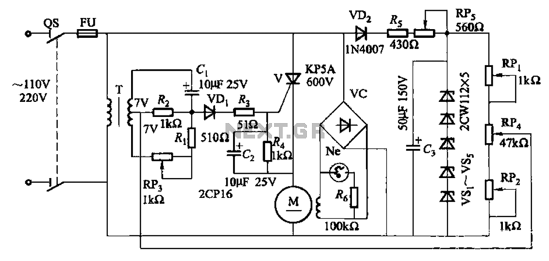
A 35W resistive and capacitive half-wave phase-shift trigger control circuit is designed for automatic or semi-automatic welding equipment to manage wire feeding and welding carriage travel. This system necessitates a drive control circuit to fulfill the welding process requirements....
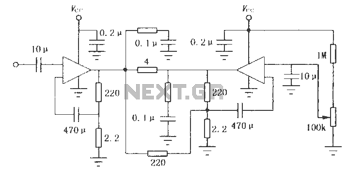
The LM2002 / 2002A is an audio power amplifier integrated circuit. The LM2002A features high voltage protection, with a maximum instantaneous power supply voltage of up to 40V, and comes in a 5-pin single in-line plastic package. This integrated...

This design outlines a simple wideband output amplifier suitable for use as a 50-ohm transmission line driver. The circuit is constructed using the CA3140 operational amplifier. When utilized alongside the function generator and sine wave shaper circuits, it delivers...
Warning: include(partials/cookie-banner.php): Failed to open stream: Permission denied in /var/www/html/nextgr/view-circuit.php on line 713
Warning: include(): Failed opening 'partials/cookie-banner.php' for inclusion (include_path='.:/usr/share/php') in /var/www/html/nextgr/view-circuit.php on line 713