
dual voltage converter turning the solar charge controller circuit

The Free Charge Controller project aims to enhance the efficiency and effectiveness of solar energy management systems. The proposed solar charge controller circuit is designed to optimize the charging of batteries from solar panels, ensuring that energy is stored efficiently while preventing overcharging and deep discharging, which can damage battery life.
The circuit typically includes several key components such as a solar panel, a battery, a charge controller IC, and various passive components like resistors and capacitors. The solar panel converts sunlight into electrical energy, which is then fed into the charge controller. The charge controller regulates the voltage and current coming from the solar panel to the battery, employing techniques such as Maximum Power Point Tracking (MPPT) or Pulse Width Modulation (PWM) to maximize energy harvest.
Protection features are integral to the design, including over-voltage protection, under-voltage protection, and temperature compensation to ensure safe operation across varying environmental conditions. Additionally, LED indicators may be included to provide visual feedback on the charging status and battery health.
The proposed circuit aims to be cost-effective and easily implementable, making it accessible for a wide range of applications, from small-scale residential setups to larger solar energy systems. Future developments may focus on integrating smart technology for remote monitoring and control, enhancing user interaction and energy management capabilities.Discusses the future direction of the Free Charge Controller project and proposes a new solar charge controller circuit.. 🔗 External reference
Related Circuits
Some time ago, a request was received for the schematic of a circuit designed to detect cut phone lines. The circuit, sourced from Electronics Now, activates a MOSFET when it detects a cut in the phone line, which can...
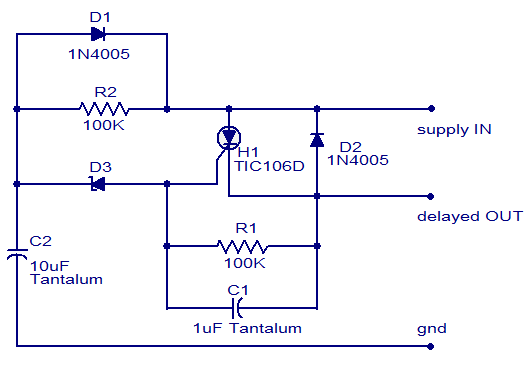
The circuit diagram presented is of a straightforward DC power delay circuit utilizing a silicon-controlled rectifier (SCR). This circuit is quite useful and can be applied in various scenarios. The operation of this circuit is uncomplicated. Upon the application...
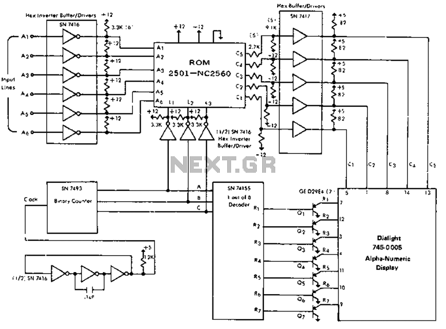
The circuit is capable of driving the company's Dialight 745-0005 monitor, which features a 64-character alphanumeric display. It generates 0-second and 1-second input signals on lines A1 through A6 based on the phase response of the desired characters, utilizing...
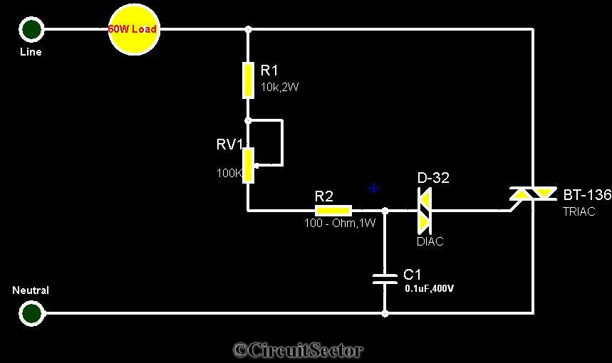
The circuit diagram presented is a triac-diac electronic fan regulator designed to reduce power consumption of electric fans, even at low speeds. Traditional resistor-inductor fan regulators tend to generate excess heat, wasting energy when the fan operates at lower...
The project demonstration has been successfully completed, with the only remaining task being the final project report due on June 15, which will be integrated with a conference paper. This update marks the last entry in the electronic notebook,...
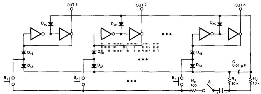
This switching circuit functions as a bank of interlocked mechanical switches. Activating one of the buttons latches its corresponding output while unlatching a previously selected output. A pair of inverters creates a latch for each output. For instance, pressing...