
35W resistive and capacitive half-wave phase-shift trigger doer control circuit
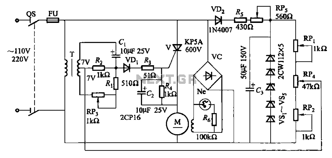
The 35W resistive and capacitive half-wave phase-shift trigger control circuit is an essential component in welding applications where precision and stability are crucial. The circuit operates by integrating a 35W DC servo motor, which provides the necessary torque and responsiveness for effective wire feeding and welding carriage movement. The use of potentiometers RPi and RPz allows for fine-tuning of the input parameters, enabling the operator to adjust the sensitivity and response of the circuit according to the welding conditions.
The voltage divider, consisting of RP4, plays a critical role in feedback regulation. By extracting a portion of the feedback voltage, RP4 ensures that the circuit can dynamically adjust to variations in load and other operational conditions. This feedback is superimposed on the AC voltage, creating a phase shift that is vital for maintaining the desired operational characteristics of the motor. The resistive and capacitive components work together to create a robust negative feedback loop, which is essential for achieving stable speed control during welding operations.
Furthermore, the adjustment of RP3 directly influences the armature voltage supplied to the servo motor. By varying this voltage, the circuit can modulate the speed of the motor, allowing for precise control over the welding process. This capability is particularly beneficial in applications that require different welding speeds for various materials or thicknesses, ensuring optimal performance and weld quality.
Overall, this control circuit exemplifies a sophisticated approach to managing the dynamics of welding equipment, leveraging phase-shifting techniques and feedback mechanisms to enhance operational efficiency and effectiveness.35W resistive and capacitive half-wave phase-shift trigger doer control circuit Automatic or semi-automatic welding equipment in order to control the wire feeding, welding car travel, requires the use of drive control circuit to meet the requirements of the welding process. (1) 35W blocking off half-wave phase-shift trigger drag the control circuit circuit is shown. Motor using 35W DC servo motor. By the potentiometer RPi, RPz and voltage divider consisting of RP4, RP4 is removed from the feedback voltage, superimposed on the AC voltage resistive and capacitive phase-shifting, to form a strong negative anti fed, stable speed control purposes. Adjust RP3, change the armature voltage, to achieve speed control purposes.
Related Circuits
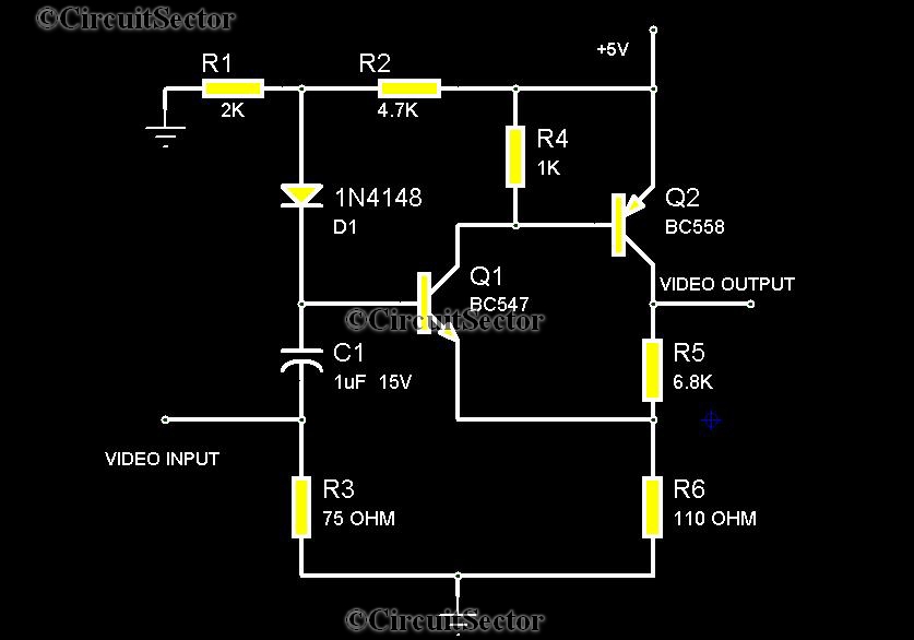
There are instances when it is necessary to view video clips captured by a digital camera on a television. This can be accomplished by connecting the camera's video output to the television's video input. However, a direct connection is...
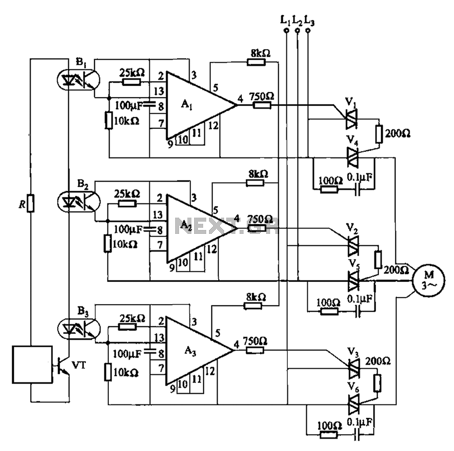
The 331 circuit depicted in the figure utilizes a two-way thyristor for controlling the start and stop functions of a motor. It operates without mechanical contacts, generating no noise or sparks, making it suitable for applications that require frequent...

When the system is placed in a shop or mall, logos and product advertisements serve as an ideal complement to temperature information. For home use, photographs of children at the beach or, should the temperature drop, images of making...
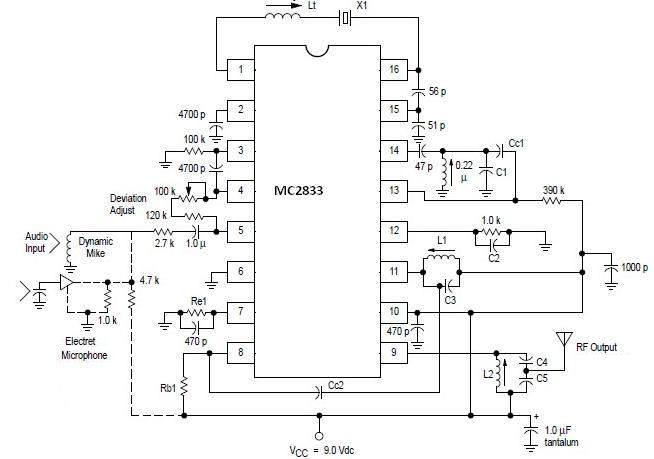
A simple FM transmitter circuit can be designed using the MC2833 integrated circuit, which is intended for cordless telephone and FM communication applications. This circuit includes a microphone amplifier, a voltage-controlled oscillator, and two auxiliary transistors. The final output...
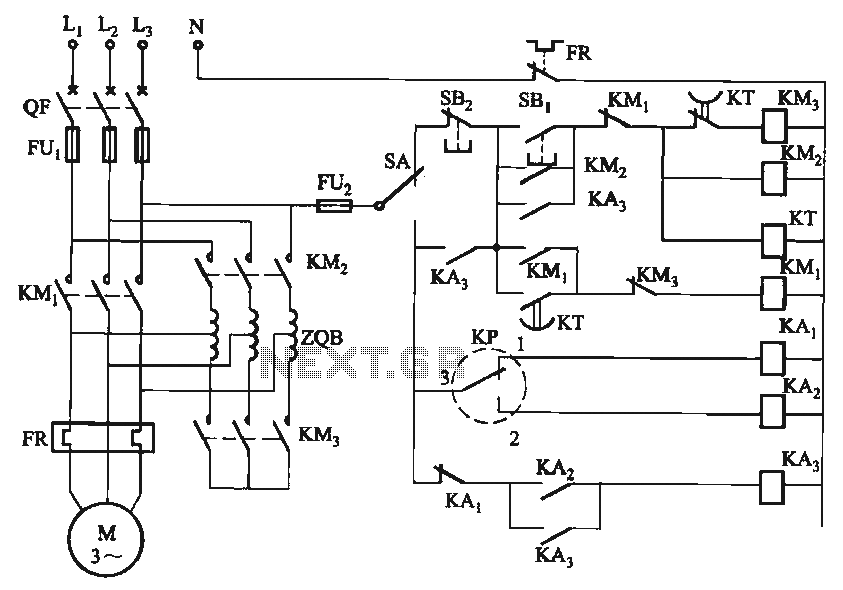
The circuit utilizes a motor auto-voltage transformer for starting. The motor auto-voltage transformer start circuit is designed to provide a controlled method for initiating the operation of an electric motor. This type of circuit is particularly beneficial in applications where...

Building a signal generator is an essential project for any analog DIY enthusiast. While already possessing a bench signal generator, the intention was to create a compact, battery-powered device for quickly testing new effect designs. An enclosure from a...