
Off TV with reed elimination circuit diagram highlights

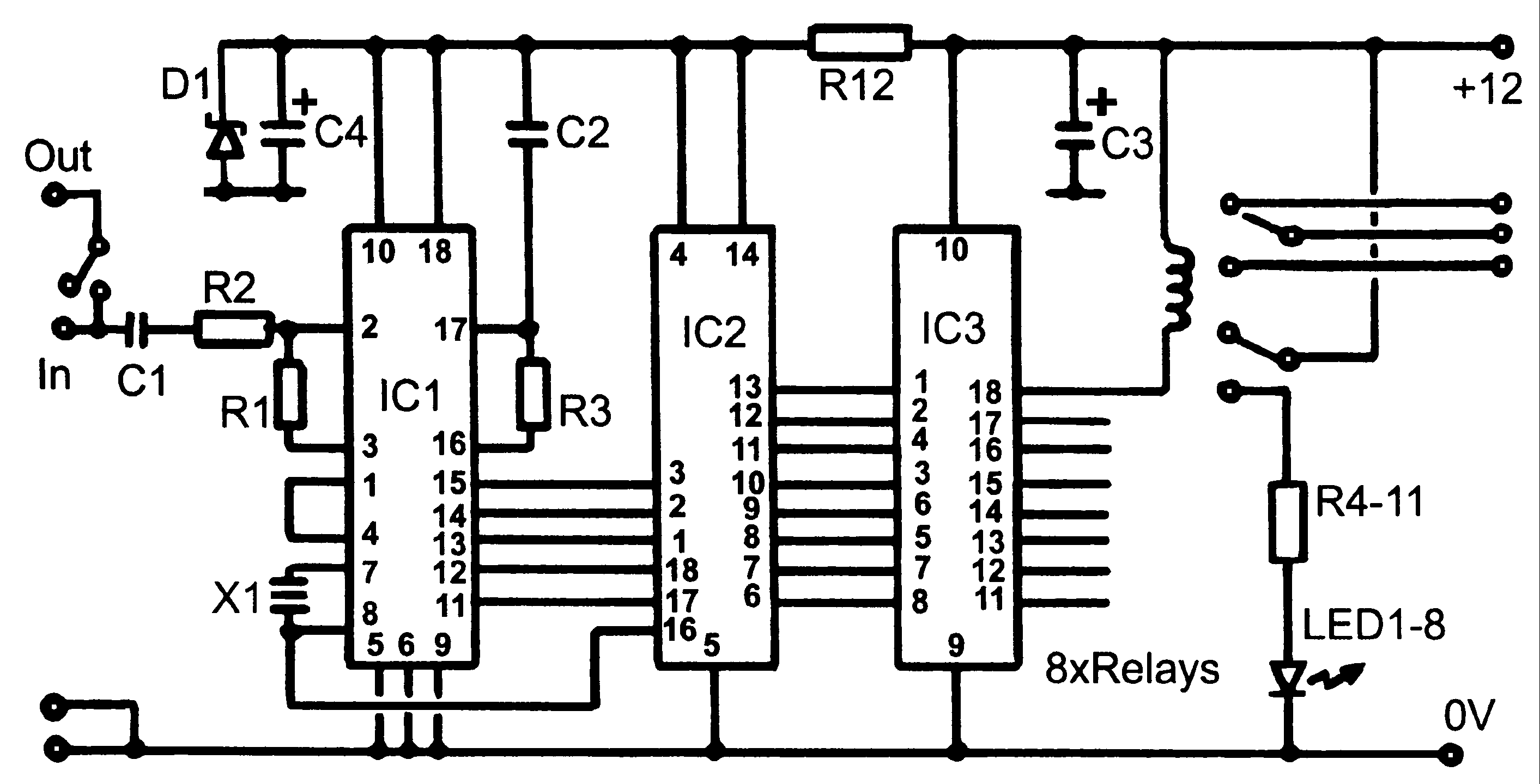
The circuit operates by integrating a reed switch, which acts as a control element to regulate the brightness of a CRT display. The brightness potentiometer allows for user-adjustable control over the circuit's operation. When the reed switch is closed, the capacitor C accumulates a high voltage, which is essential for maintaining the required cathode voltage in the CRT. This voltage enables the display to function correctly by allowing the electron beam to strike the phosphorescent screen.
Upon deactivation of the circuit, the opening of the reed switch interrupts the charging path of the capacitor. The significant capacitance of C plays a crucial role in sustaining the cathode voltage momentarily even after the power is removed. This retention of voltage ensures that the electron beam is effectively cut off, thereby preventing any residual highlights from appearing on the screen.
The inclusion of a coil around the reed switch serves to enhance the magnetic field interaction, which can improve the reliability and responsiveness of the reed switch operation. The use of 0.1mm enameled wire with 5200 turns allows for a compact yet effective design, optimizing the inductance and ensuring that the coil generates a sufficient magnetic field when energized. One terminal of the coil is grounded, providing a return path, while the other is connected to the +12V power supply, ensuring that the circuit operates within the appropriate voltage range.
Overall, this circuit design effectively addresses the issue of highlight elimination in CRT displays, leveraging the properties of capacitors and reed switches in conjunction with a carefully designed coil to achieve desired performance outcomes. As shown by a reed switch off the TV highlights cancellation circuit. Brightness potentiometer W ground a series reed, normally watch TV, the reed contact is closed, the capaci tor C charging voltage of about 160V. Shutdown, reed contacts open, since the larger capacity C, and its main tributary discharge has been cut off, so that the CRT cathode voltage will be retained for a period of time to cut an electron beam to achieve the purpose of eliminating the highlights. Reed should be added around the outside of a coil, the coil frame including enamelled with 0.1MM tightly wound 5200 turns coil end of the ground, and the other termination power + 12V.
Related Circuits
Control monitoring equipment at a TV repeater site is designed to accept commands sent as DTMF tones over the repeater's audio channel. It is capable of switching either AV signals or power supply feeds with currents up to 1...
The PLL synthesizer oscillator circuit is a feedback loop consisting of a reference oscillator, phase comparator, loop filter, voltage-controlled oscillator, programmable frequency divider, and various other components. In this circuit, the reference oscillator employs a crystal oscillator (OSC) to...
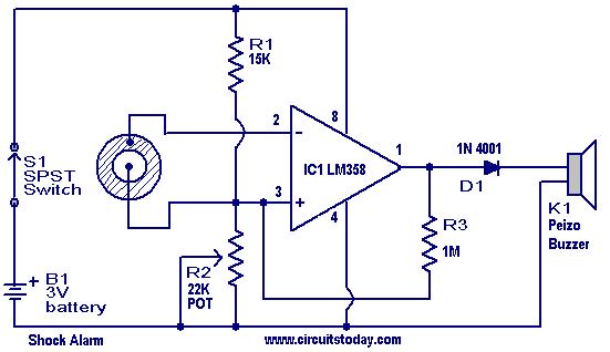
This is a simple shock-sensitive alarm circuit with numerous applications, ranging from home use to automobiles. The primary application of this circuit is as an anti-theft alarm for vehicles. A piezoelectric sensor is employed as the shock sensor and...
While developing an infrared (IR) extender circuit, a method was needed to measure the relative intensities of different infrared light sources. This circuit utilizes an SFH2030 photodiode as the infrared sensor. A CA3140 MOSFET operational amplifier is employed in...
1997 Toyota Camry Fuel Pump Wiring Diagram. The fuel pump wiring diagram for the 1997 Toyota Camry provides a detailed representation of the electrical connections associated with the vehicle's fuel pump system. This diagram typically includes the power supply lines,...
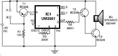
The UM3561 integrated circuit can be utilized to design various alarm systems with minimal electronic components. This UM3561 alarm electronic project requires only a few electronic parts and operates on a simple 3 volts DC power supply. The UM3561 is...