
DTMF Control circuit
The control monitoring equipment operates by interpreting DTMF tones transmitted over the audio channel of the repeater. The design integrates a relay-based switching mechanism to manage both audio and power supply feeds effectively. The use of BT53 relays allows for reliable operation within the specified current limits. The monitoring LED serves as a visual indicator of relay status, enhancing operational feedback.
The 8870 tone decoder chip plays a critical role in ensuring the accuracy of command recognition. Its decision-making capability to confirm the presence of both tones for a specified duration minimizes false positives, which is essential for maintaining the integrity of the control system. The integration of the 16C84 microcontroller facilitates the processing of decoded signals, enabling precise control over the relays based on the received command sequences.
The design's consideration for compatibility with existing MF control systems, such as GB3XG and GB3ZZ, demonstrates a forward-thinking approach, allowing for future expansion and adaptability. The timeout mechanism further enhances system reliability by preventing unintended relay activation due to incomplete command sequences.
The inclusion of the ULN2803 driver IC not only simplifies the circuit by reducing the need for additional components but also enhances the overall robustness of the design by ensuring that the relay coils are adequately driven without overloading the microcontroller's output pins.
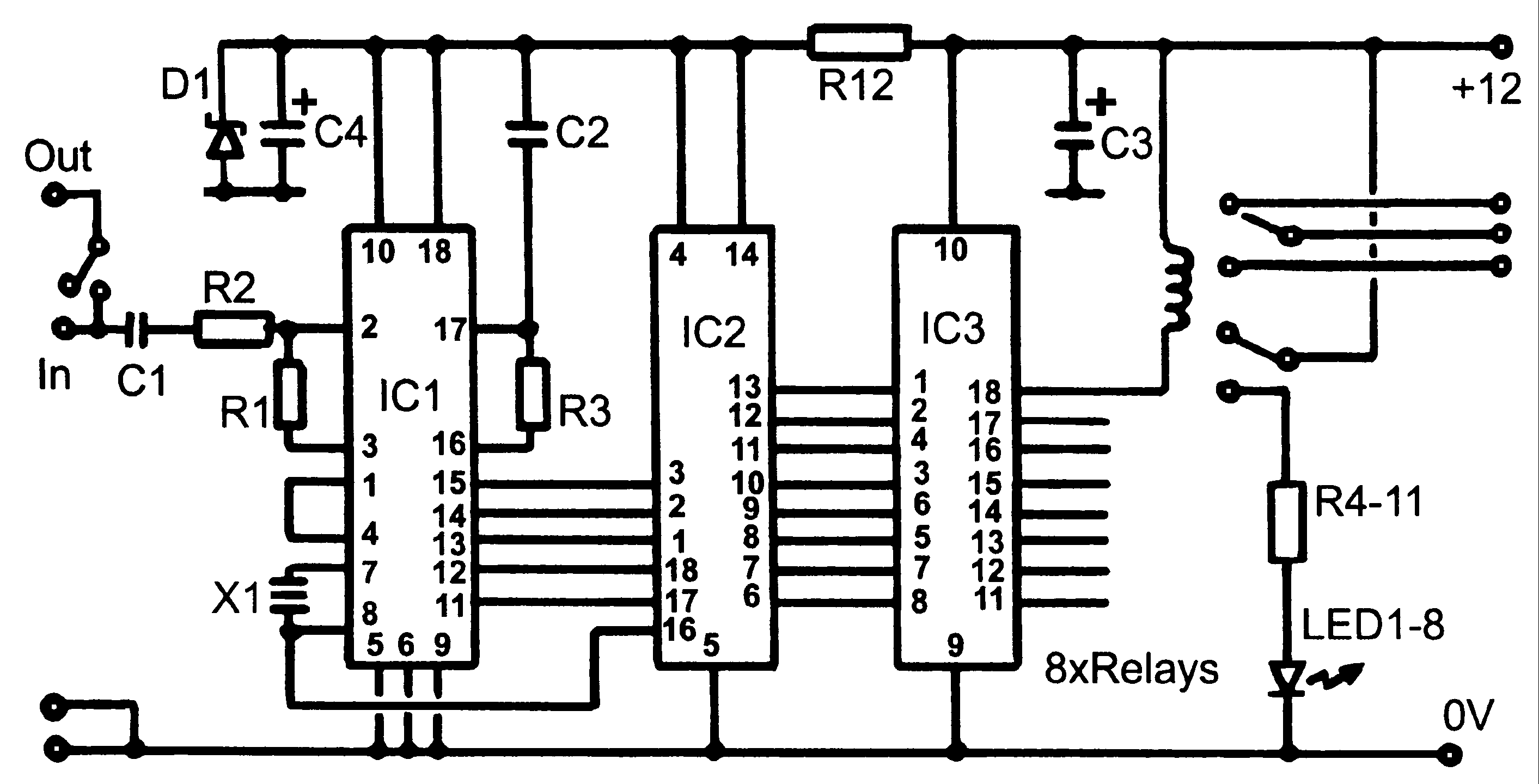
In summary, this control monitoring equipment represents a versatile and efficient solution for managing audio and power supply feeds at a TV repeater site, with features that ensure compatibility, reliability, and ease of modification for future enhancements.Control monitoring equipment at a TV repeater site. It had to accept commands sent as DTMF tones over the repeaters audio channel and be able to switch either AV signals or power supply feeds at currents up to 1 Amp. The switching requirements left no option but to use relays and the cheap and easily available BT53 ” style was chosen.
As these are two pole relays but only one was called for, the other was put to use to drive a monitoring LED. The LED is illuminated when the relay is energised. It is simple to modify the the wiring to allow both poles to be used if the LED facility isn ’t needed. The design specification stated that the unit should co-exist with other MF controlled equipment, specifically, the single MF tone pair commands that GB3XG used and the sequence of four tones that GB3ZZ used.
When I wrote the operating system for GB3ZZ over a decade ago, I deliberately left a gap in the valid command sequence "for future developments ”. In hindsight, this was a good idea as it left space for commands this unit could use. The range of MF commands available is *50# through to *59# although this can easily be changed by modifying the source code and re-assembling the PIC program.
Unfortunately, GB3XG uses single tone commands so for example, keying *52# would be seen as four individual instructions that could have left the repeater performing unwanted actions. To overcome this problem, the audio feed to the repeater had to be disconnected as soon as the * ” was seen and then reconnected after the # ” was received.
One of the relays is used for this purpose. The audio is looped through the board and interrupted for the duration of the command sequence. All the other relays have accessible changeover switch contacts (note: SK6 and SK7 have reversed pin-outs) and are available for general-purpose use. To make the unit as versatile as possible, the relays operate in different ways. Some are selected as one of four ”, some are turned on with one code and off with another and one relay has a timed period before switching itself off.
The industry standard 8870 chip performs the decoding of audio tones to a binary number. The chip not only filters the audio but also uses a clever ‘decision ’ process to check that both tones are present for at least 40mS. When it has decided that a genuine MF signal has been received it decodes it to a binary number and signals it has done so by raising a tone detected ” (strobe) pin.
The binary number and strobe signals are fed to the 16C84 device, which reads the signals in through its RA (port A) pins. It checks to see if the tone corresponded with the * ” digit and if so, it disconnects the downstream audio by operating relay 1 then starts a five second time-out counter.
If the following digits are in the 50 to 59 range and received within the five seconds, it drives the appropriate RB (port B) pin high or low to operate one of the relays. If the 5-second period runs out before the remaining digits have been received, it purges any that did get through and turns the audio back on again.
This technique lessens the chance of an incomplete sequence being finished inadvertently at a later time. The RB pins are capable of driving the relay coils directly but would be pushed close to their limits to do so.
To ease the strain on them, a ULN2803 driver IC is used which also has the benefit of having clamp diodes on each output. This eliminates the need to add eight diodes, one across each of the relay coils to snub any back voltage as the relay de-energises.
The remainder of the circuit consists of LEDs and current limiting resistors to show which relays are active. These can be omitted if desired. The unit runs on a 12V supply but can be modified to run on 5V if the relays are replaced with ones having a 5V coil rating.
The D1 can then be omitted and R12 replaced with a link. I have not 🔗 External reference
Related Circuits
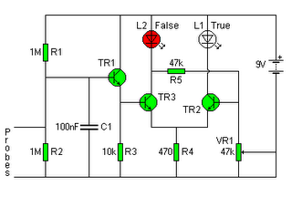
The following circuit illustrates a Lie Detector Circuit Diagram. Features include a capacitor that eliminates the 50Hz induced mains hum present in the circuit. The Lie Detector Circuit operates on the principle of measuring physiological responses, typically galvanic skin response...
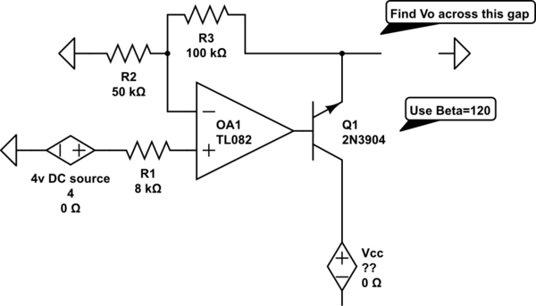
The voltage measured at 12V after the emitter is perplexing, especially when the output from the op-amp is +15V, suggesting a 3V drop across the transistor. This raises questions about the expected gain of 2, which would imply an...

The circuit for the bridge excitation voltage XTR108 is linearized using adjusted algorithms that correspond to the linearization of the RTD response. The excitation voltage VEX is defined as 2IREFR1, where VEX represents the excitation voltage applied at both...

This switch utilizes four CD4013BE dual flip-flops, an inverter, and an optoisolator to control a triac, allowing it to switch a 25-A AC load current. A standard 4x3 telephone keypad is employed for entering a 6-digit code. In the...
This schematic illustrates an infrared (IR) transmitter circuit utilizing an integrated circuit (IC). The circuit employs the widely recognized NE555 timer IC, which operates as an astable multivibrator to generate a signal with a frequency of 38 kHz. The...

A typical circuit for welding equipment is illustrated in the following circuit diagram. The turn-on delay can be accurately controlled with Potentiometer P2, allowing for effective discharge management. The welding equipment circuit typically incorporates several key components to ensure proper...