
Shock alarm circuit

This shock-sensitive alarm circuit utilizes a piezoelectric sensor to detect vibrations, making it highly effective for applications in security systems. The piezoelectric sensor generates a voltage when subjected to mechanical stress, which is central to the operation of the alarm. The LM358 operational amplifier, configured as an inverting Schmitt Trigger, provides hysteresis, allowing the circuit to have a defined threshold for activation and deactivation.
The potentiometer R1 plays a crucial role in setting the sensitivity of the circuit. By adjusting R1, the user can define the minimum level of vibration required to trigger the alarm, making it adaptable to various environments and levels of sensitivity needed.
When the sensor detects a shock, the output voltage from the piezoelectric sensor rises above the threshold set by R1, which causes the output of the LM358 to switch from low to high. This transition activates the buzzer, alerting the user to potential unauthorized access or tampering. The design ensures that once triggered, the buzzer continues to sound for a predetermined duration, providing an effective deterrent against theft or intrusion.
The circuit can be powered by a standard DC supply, and it is advisable to include protection components such as diodes to prevent damage from voltage spikes. The integration of a capacitor across the output may also be considered to control the duration of the buzzer sound, depending on the application requirements. Overall, this circuit is a reliable and straightforward solution for enhancing security in various settings.Here is a simple shock sensitive alarm circuit that has many many applications fro home to automobiles. The main application of this circuit is to use it as an anti theft alarm in automobiles. A peizo electric sensor is used as the shock sensor which has to mounted on the door which you have to protect.
Here the IC1 LM 3558 is wired as an inverting Schmitt Trigger. The POT R1 sets the threshold voltage of the circuit. R1 is used as a feed back resistor. When not activated the out put from the piezo sensor will be low and so do the output of the IC. When the piezo sensor is activated its output voltage goes high and triggers the Schmitt trigger. This results the beeping of the buzzer. The buzzer remains beeping for some time even if the vibration is removed. this is because the increase in the inverting input has little effect when the IC is triggered and the state can`t be easily reversed. 🔗 External reference
Related Circuits

CA3600E array transistor pair and a reverse CA3080 operational amplifier are used together to provide precise timing and thresholds for the square wave. A typical static power consumption is 6mW. The CA3600E is a versatile integrated circuit that includes multiple...

A flash memory schematic can be created using various reset sources, including power-on reset, external reset, software reset, watchdog timer reset, and brownout reset. The accompanying figure illustrates a recommended external reset circuit for the MSC1210, which includes a...

This disco lamp circuit is not a voice-operated switch (VOX) because it cannot differentiate between musical sounds and human voices. Instead, it is sound-activated. An interesting application of this circuit is to control disco lighting automatically using the musical...
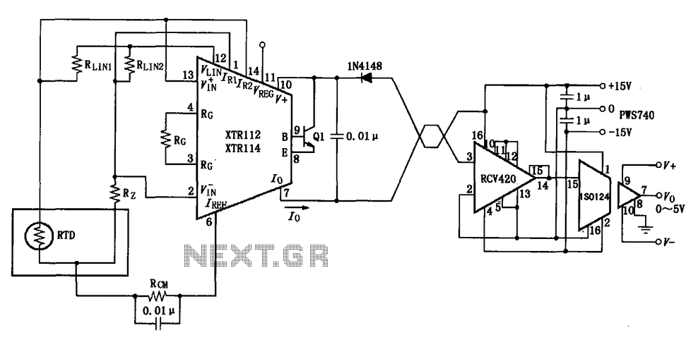
The RTD temperature data collected at the scene is converted into a voltage using the XTR112/114. This voltage is further transformed into a 4 to 20 mA current output, which is then transmitted via a twisted pair. The RCV420...

Lux meter circuit using an Atmel ATtiny26-16 microcontroller, which displays lux values on an LED display. The circuit utilizes 2SK1061 MOSFETs for driving the LEDs. The lux meter circuit operates by measuring ambient light levels and converting these measurements into...

The circuit depicted utilizes the UPC1651 integrated circuit produced by NEC Corporation of Japan. It offers high gain and stability, ensuring optimal performance for microphones. The design incorporates an FM transmitter circuit. The system employs a flexible antenna measuring...