
Flash light emitting diode display circuit

This circuit employs a multivibrator configuration, typically a 555 timer IC or a similar component, to generate a square wave output that drives one or more light-emitting diodes (LEDs). The multivibrator can be configured in astable mode, which allows it to continuously oscillate between high and low states, thereby producing a flashing effect.
In the proposed circuit, the 555 timer is connected with appropriate resistors and capacitors to set the desired frequency of the flashing LEDs. The output pin of the timer is connected to the anode of the LED, while the cathode is connected to ground through a current-limiting resistor. This resistor is crucial as it ensures that the current flowing through the LED does not exceed its maximum rating, thus preventing damage.
Additionally, the circuit can be enhanced by incorporating multiple LEDs in parallel or series to create various visual effects, such as simulating the blinking of eyes. The choice of LED colors can also be varied to achieve different aesthetic results.
Powering the circuit can be accomplished using batteries or a DC power supply, depending on the intended application. For toys, a compact battery solution is often preferred for portability.
In summary, this multivibrator-based LED display driver circuit provides an engaging visual effect suitable for toy applications, effectively simulating the blinking of eyes in animals or monsters. As shown by the multivibrator flashing light emitting diode display driver circuit can be used in toys in the eyes of animals or monsters double eyes flash.
Related Circuits

The AC input circuit functions as a converter, transforming an alternating current (AC) signal into a direct current (DC) signal, which is subsequently processed by an analog-to-digital (A/D) converter chip. The input circuit is designed to handle AC signals, typically...

The circuit illustrated in Figure 3-123 operates as follows: When the stop button SBz is pressed, contact KMi releases, cutting off power to the motor. Simultaneously, KMz is activated, engaging the electromagnetic brake YB to hold the motor in...

This device enables two computers to share a single USB printer or other USB devices such as an external flash drive, memory card reader, or scanner. A rotary switch is used to select the PC that will connect to...

The circuit is capable of supplying either a trickle charge (50 mA) or a high-current charge (1 A). Users can select either charging method or an automatic mode that initially trickle charges a battery if it is particularly low...
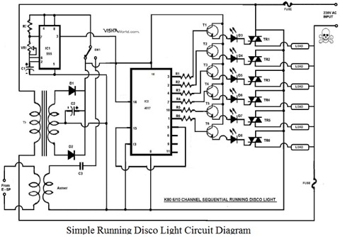
This article explains how to design a minimal Running Disco Light Circuit Diagram using the IC 4017. The IC 4017 is a 16-pin dual in-line package integrated circuit that includes a 10-stage decade counter. The design operates on 230V...

This is a circuit design for an FSK demodulator, which is an electronic device that converts an FSK signal into a serial digital signal. FSK modulation is used to transmit digital serial data, and demodulation is necessary to retrieve...
Warning: include(partials/cookie-banner.php): Failed to open stream: Permission denied in /var/www/html/nextgr/view-circuit.php on line 713
Warning: include(): Failed opening 'partials/cookie-banner.php' for inclusion (include_path='.:/usr/share/php') in /var/www/html/nextgr/view-circuit.php on line 713