
ICL7107 chip digital circuit section 2
The input circuit is designed to handle AC signals, typically sourced from mains voltage or other alternating sources. The first stage of the circuit involves a rectifier, which converts the AC signal into a DC signal. This rectification can be achieved using a full-wave bridge rectifier configuration, which consists of four diodes arranged in a bridge layout. This configuration ensures that regardless of the polarity of the input AC signal, the output will always be a positive DC voltage.
Following the rectification process, a filtering stage is employed to smooth the pulsating DC output. This is typically done using capacitors, which charge during the peaks of the rectified signal and discharge during the troughs, effectively reducing the ripple voltage and providing a more stable DC output. Depending on the application, additional filtering stages, such as inductors or more capacitors, may be included to further enhance the quality of the DC signal.
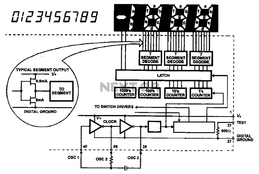
Once the AC signal has been successfully converted and stabilized as a DC signal, it is fed into the A/D converter chip. The A/D converter is responsible for sampling the DC voltage at specific intervals and converting it into a digital representation, which can then be processed by a microcontroller or other digital circuitry. The resolution and sampling rate of the A/D converter will determine the accuracy and responsiveness of the digital output.
In summary, the circuit effectively transforms an AC input into a clean and stable DC signal suitable for digital processing, ensuring accurate measurements and reliable performance in various electronic applications.AC has been shown as a fishing converter input circuit ND conversion Tiger Road. In order to check the AC signal and I was shown, it is provided in the input circuit AC DC conv erter circuit, the first AC signal into a DC signal, and then into the A/D converter chip.
Related Circuits
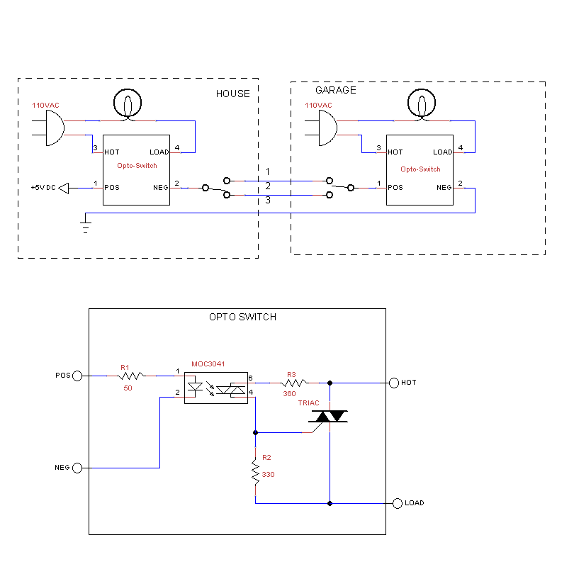
The rewiring of an entire house is underway following a significant malfunction of two antique knob and tube circuits. A challenge has arisen with the outdoor lighting setup, specifically concerning a detached garage that features a porch light above...
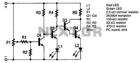
This LED flasher circuit is a classic two-transistor flip-flop. It is a popular circuit often built by beginners in electronic circuit design. The schematic diagram of this well-known LED flasher circuit consists of two transistors, two capacitors, four resistors,...
The monitor functions as a basic voltage comparator, utilizing a car battery as its power source. The input voltage to the comparator is adjusted using potentiometer PI. This adjustment ensures that the green LED L2 illuminates when the alternator...

The local oscillator operates at frequencies of 1 GHz or higher, utilizing a common collector circuit, which makes it challenging to generate low-frequency self-oscillation. Typically, the local oscillator signal is passed through a buffer amplifier stage before being applied...
The LAN tester circuit can also test cables such as telephone, coaxial, LAN, and others. This circuit uses LEDs as the main indicator device. The LAN tester circuit is designed to verify the integrity and functionality of various types of...

Due to limited space, a small 6V battery is utilized, and the voltage is reduced by 1.2V to 4.8V using diodes D1 and D2. The PicAxe chip is employed in the circuit. In this circuit design, the primary power source...