
Battery Charger Circuit
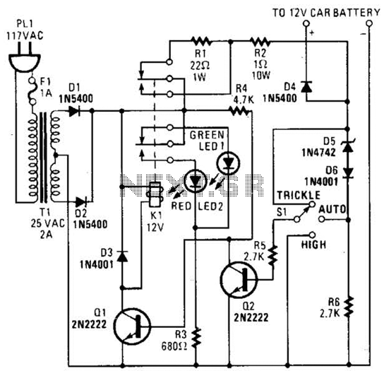
The circuit employs a dual charging mechanism, allowing for flexibility in battery management. The trickle charge mode is particularly useful for maintaining battery health when the voltage is low, ensuring that the battery is not subjected to excessive current that could lead to damage. The presence of Zener diode D5 is critical; it regulates the voltage and ensures that the charging process is safe and efficient. When the battery voltage is low, the Zener diode does not allow enough current to pass through R6 to activate Q2. This condition allows Q1 to be turned on, engaging relay K1 and establishing a path for the trickle charge through R1.
As the battery voltage rises, the functionality of the circuit transitions seamlessly. The increased current through D5 generates a voltage drop across R6, which activates Q2. This action effectively disables Q1, disengaging relay K1 and shifting the circuit back to a high-current charging mode. This design ensures that the battery receives an appropriate amount of charge without the risk of overcharging, as the system automatically adjusts the charging current based on the battery's state. The use of resistors R1, R2, R4, and R6 in conjunction with the transistors and relay provides a robust control mechanism for managing the charging process, optimizing battery performance, and prolonging its lifespan. The circuit is capable of supplying either a trickle (50 mA) or high-current (1-A) charge. You can select either charging method or an automatic mode that will first trickle charge a battery if it is particularly low before switching to high-current charging.If the battery`s voltage is low, Zener-diode D5 will not conduct sufficient current to produce a voltage drop across R6 to turn Q2 on. With Q2 off, R4 pulls the base of Ql high, turning it on. That activates Kl. With K1 active, the only thing between the battery and the power supply is R2 and D4 (which prevents current from flowing through the circuit from the battery).
Once the battery charges a bit, the current through D5 increases, causing a voltage drop across R6 that is of sufficient magnitude to turn on Q2. Transistor Q2, in turn, grounds the base of Ql, keeping it off. With Ql off, Kl remains in its normally closed state. That places Rl in series with the battery, thereby reducing the current to a trickle. 🔗 External reference
Related Circuits
When light strikes the Light Dependent Resistor (LDR), its resistance decreases significantly. The voltage at the junction of the LDR and resistor R2 gradually charges capacitor C2 through resistor R1. After approximately 10 seconds, the voltage across the capacitor...
The circuit described is designed to activate a lamp when the telephone rings, provided that the ambient light is insufficient. It utilizes two integrated circuits (ICs) and can be implemented with ease. At the core of the circuit is...
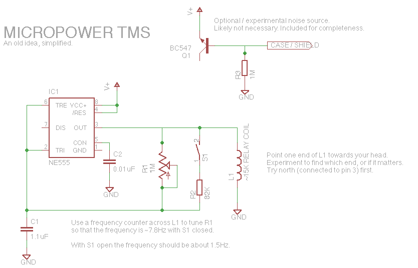
Let's face it, not every day is the greatest. Sometimes, one may not feel like doing much of anything. Wouldn't it be nice if there was a way to change brain waves at the push of a button? Transcranial...
The circuit consists of two synchronized multivibrators formed by a pair of 555 timer circuits. It is capable of generating two synchronized pulse signals, with the spacing and frequency adjustable by modifying the time constant. The circuit offers flexibility...
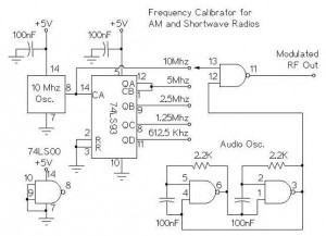
The following circuit illustrates an AM/Shortwave Radio Frequency Calibrator Circuit Diagram. This circuit is based on the 74LS93 IC. Features: The .. The AM/Shortwave Radio Frequency Calibrator Circuit utilizes the 74LS93 integrated circuit, which is a 4-bit binary counter. This...
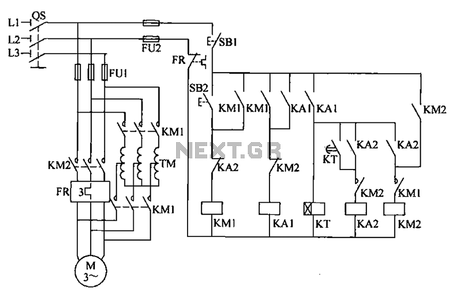
To initiate the system, turn off the power switch, then press the start button SB2. The KM1 contactor is energized, engaging self-locking, and closing the main contacts. The autotransformer TM is connected between the power source and the motor,...
Warning: include(partials/cookie-banner.php): Failed to open stream: Permission denied in /var/www/html/nextgr/view-circuit.php on line 713
Warning: include(): Failed opening 'partials/cookie-banner.php' for inclusion (include_path='.:/usr/share/php') in /var/www/html/nextgr/view-circuit.php on line 713