
TDA8350Q test circuit diagram
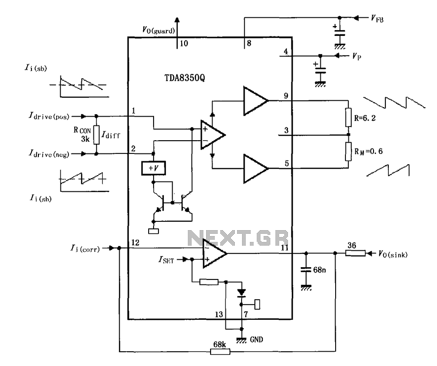
The TDA8350Q is a high-performance integrated circuit designed for use in television and display systems. In the context of the test circuit, it is configured as a push-pull amplifier, which effectively drives the output stage to deliver the necessary power to the load. The use of a push-pull arrangement allows for improved efficiency and reduced distortion in the output signal.
In this specific setup, the output terminal resistor plays a crucial role as a dummy load. This is particularly important for testing the performance of alternative deflection coils, which are essential components in CRT (Cathode Ray Tube) displays. The dummy load simulates the characteristics of a real deflection coil, allowing for accurate assessment of the amplifier's performance without the need for a physical coil during testing.
The circuit typically includes input and feedback components to stabilize the amplifier and ensure linear operation. The TDA8350Q will require appropriate biasing to operate in its optimal range, and the values of the resistors and capacitors used in the circuit must be carefully selected to match the specifications of the deflection coil being tested.
Overall, this configuration allows engineers to evaluate the amplifier's output capabilities, thermal performance, and response characteristics under controlled conditions, facilitating the development and troubleshooting of display systems. As shown for the TDA8350Q test circuit, the circuit is in the push-pull amplifier output terminal resistor as a dummy load testing alternative deflection coil.
Related Circuits
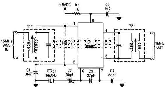
This simple frequency converter mixes the 15-MHz WWV/WVH signal with a 16-MHz signal from the local oscillator (LO) to convert it down to 1 MHz, enabling it to be received on an AM-band receiver. The frequency converter operates by utilizing...

The coil must invert the signal a second time to ensure that the feedback is positive, which will cause the circuit to oscillate on and off. In electronic circuits, particularly in oscillator designs, the feedback mechanism plays a crucial role...
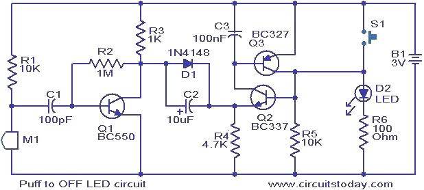
This circuit features an LED that can be turned off with a puff of air. A condenser microphone (M1) detects the puff. When the push button switch S1 is activated, transistors Q2 and Q3, configured as a latching pair,...
This precise one-pulse-per-second clock is constructed using a few common components and is driven by a 50 or 60 Hertz mains supply, without any direct connection to it. It produces a beep or metronome-like click and/or a visible flash...
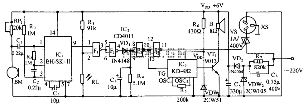
The circuit illustrated includes a sound transducer sensing switch, an electrical light control switch, an SCR control circuit, a vocal music circuit, and an AC step-down rectifier circuit. The circuit comprises several interconnected components that serve distinct functions, allowing for...
Also known as the Free lamp (commonly referred to as the Myanmar lamp by online sellers), this device operates using the voltage from a standard household fixed telephone line, eliminating the need for batteries or AC power. The lamp...