
Puff to OFF LED circuit
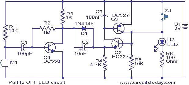
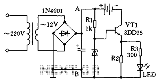
This circuit design utilizes a condenser microphone as a sound sensor, which is sensitive to air pressure changes. When a user blows air towards the microphone, the resulting sound pressure generates a voltage signal. This signal is then amplified by transistor Q1, which serves as a signal conditioner to ensure that the voltage level is sufficient to influence the state of the latching pair formed by transistors Q2 and Q3.
The latching configuration allows the circuit to maintain its state (LED ON) even after the push button S1 is released. This is achieved through positive feedback, where the output of one transistor feeds into the base of the other, creating a stable ON condition. The transition from ON to OFF is triggered by the amplified signal from the condenser microphone. When the microphone detects a puff, the output voltage from Q1 effectively disrupts the latching condition, causing both transistors Q2 and Q3 to turn off, which in turn turns off the LED.
This circuit is particularly useful in applications where hands-free operation is desired, allowing users to control the LED with a simple puff of air. The design can be further enhanced by incorporating additional features such as adjustable sensitivity for the microphone, using a potentiometer in the circuit to fine-tune the threshold for detecting puffs, or integrating a delay circuit to prevent accidental triggering from ambient noise. Overall, this simple yet effective circuit demonstrates the principles of sound sensing and transistor latching in electronic design.This is a simple circuit in which the glowing LED can be switched OFF just by a puff. A condenser mic (M1) is used to sense your puff. When the push button S1 is pressed, the transistors Q2 and Q3 wired as latching pair gets activated and drives the LED to glow. The LED remains in this condition. When you puff on the condenser mic, the sound press ure is converted into a voltage signal at its output. This voltage signal will be amplified by the transistor Q1. Since the collector of the Q1 is coupled to the emitter of the latching pair, the pair will stop conducting when ever there is a signal from the condenser mic due to puffing and the LED will go OFF. The push button switch S1 has to be pressed again to switch the LED ON. 🔗 External reference
Related Circuits
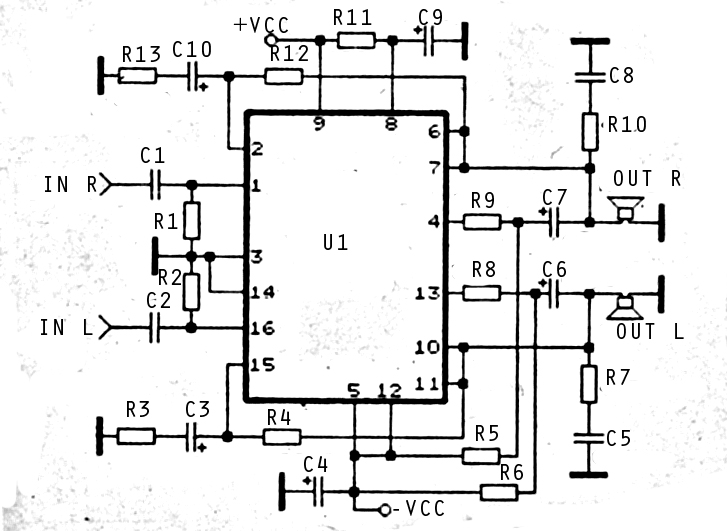
The audio amplifier circuit is highly suitable for home use, particularly with subwoofer or woofer speakers. Commonly referred to as a home amplifier, these audio amplifiers are based on integrated circuits (ICs), specifically the STK series, which includes models...
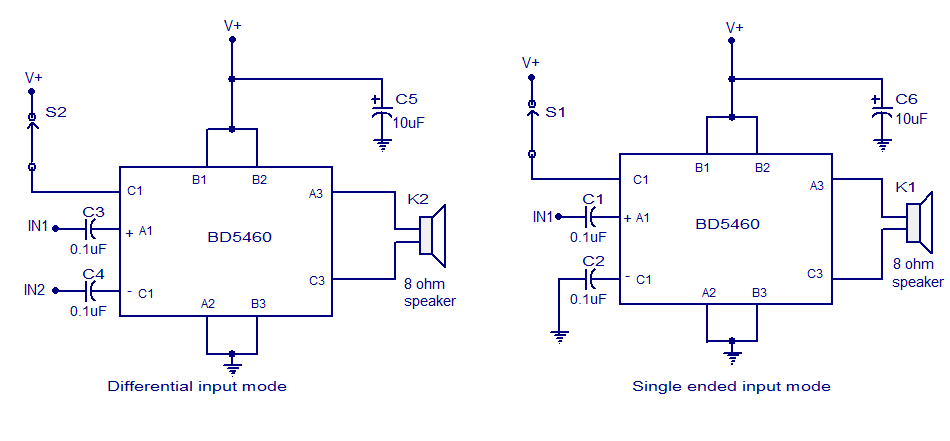
The BD5460 is a low power Class D amplifier that can be utilized in low power applications such as handheld audio devices. The BD5460 does not require an LC filter at the speaker output and can be powered by...
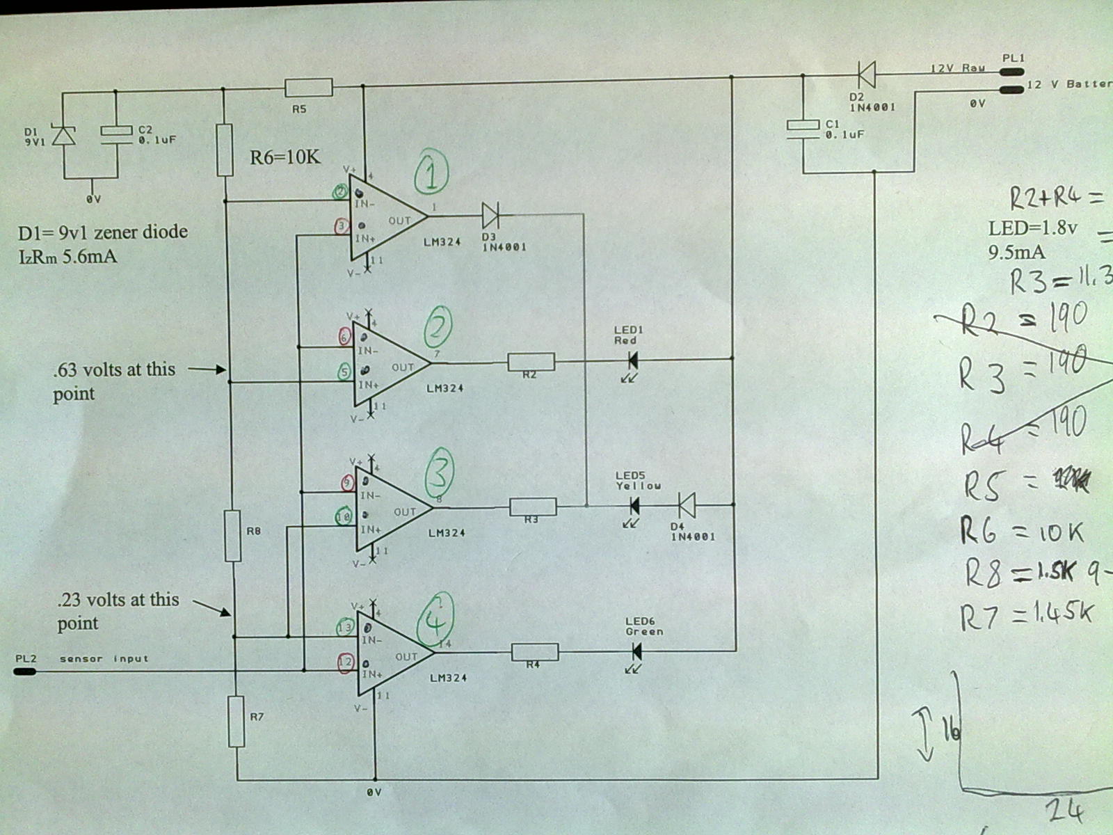
A 12V power supply is connected to the positive terminal, allowing current to flow through a protection diode and a capacitor that smooths the voltage. A zener resistor (R5) limits the current to the zener diode, which regulates the...
A practical single-tube constant current charger is illustrated, utilizing a transistor (VT1) that plays a crucial role in maintaining a constant current. The current value is determined by the voltage regulator and resistor R2. The general output voltage is...
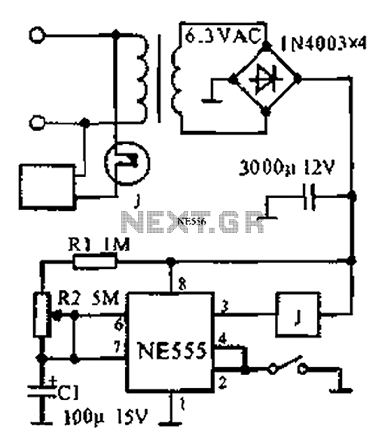
The provided information indicates that when the power supply operates between 0 to 1 hour, an AC circuit diagram is established using a 555 timer configured as a one-hour timer. The relay utilized is a J 212 IRC MR312C...
The 22-watt amplifier is straightforward to construct and cost-effective. This circuit can serve as a booster in a car audio system, an amplifier for satellite speakers in a surround sound or home theater setup, or as an amplifier for...
Warning: include(partials/cookie-banner.php): Failed to open stream: Permission denied in /var/www/html/nextgr/view-circuit.php on line 713
Warning: include(): Failed opening 'partials/cookie-banner.php' for inclusion (include_path='.:/usr/share/php') in /var/www/html/nextgr/view-circuit.php on line 713