
Sine wave schematic
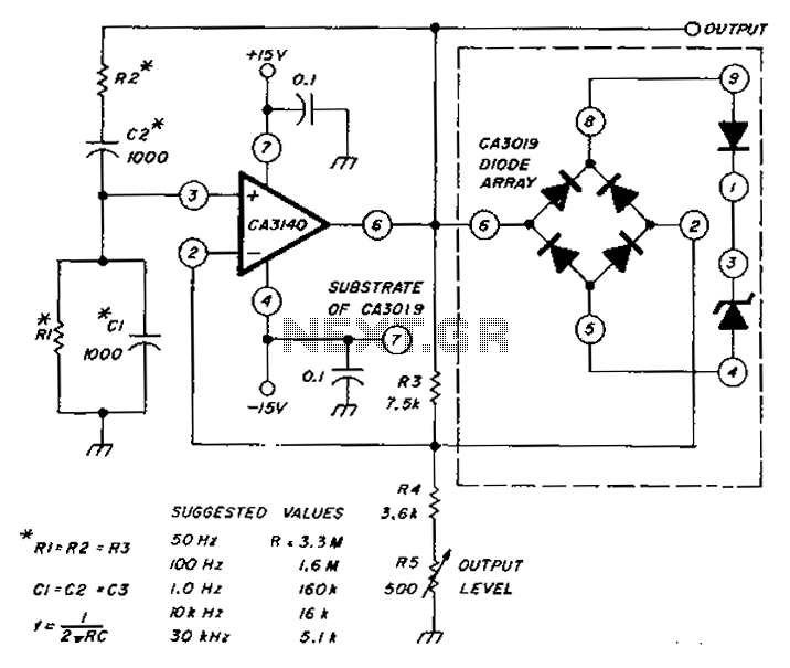
The circuit leverages the CA3140 op-amp, known for its high input impedance and low bias current, making it suitable for applications requiring precision in signal processing. The diode array serves to shape the output waveform, ensuring minimal distortion during sine wave generation. The configuration of resistors and capacitors is critical; they determine the frequency response of the circuit. By adjusting these components, the circuit can be tuned to produce sine waves at specified frequencies across the range of 50 Hz to 30 kHz.
The inclusion of a Zener diode plays a pivotal role in maintaining amplitude stability. It acts as a voltage reference, clamping the output to prevent excessive amplitude variations. This feature is essential for applications where consistent signal levels are required. The quick automatic gain control (AGC) mechanism is facilitated by the diode array, allowing for rapid adjustments in gain to accommodate varying input signal levels, thus enhancing the reliability of the sine wave output.
Overall, this circuit design is advantageous for audio applications, signal generators, and other electronic systems where low distortion and precise frequency generation are necessary. The combination of the CA3140 op-amp, carefully selected R and C values, and the diode array with Zener diode ensures a robust and efficient sine wave generation system. Circuit diagram used CA3140 op amp and diode array, produces a low distortion sine wave. Table shows the values of R and C, access to frequencies from 50Hz to 30kHz. Zener diod e clamp for amplitude control, and provide quick AGC.
Related Circuits
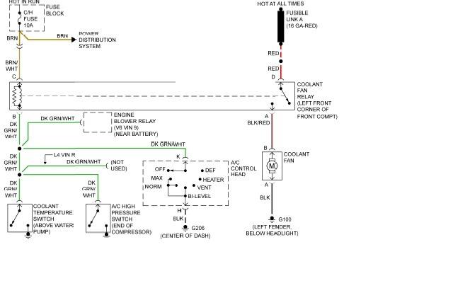
The following page outlines detailed information and the schematic of the 1985 Pontiac Fiero Wiring Diagram and Electrical System. The electrical system consists of: The 1985 Pontiac Fiero features a complex electrical system designed to support various components and functionalities...
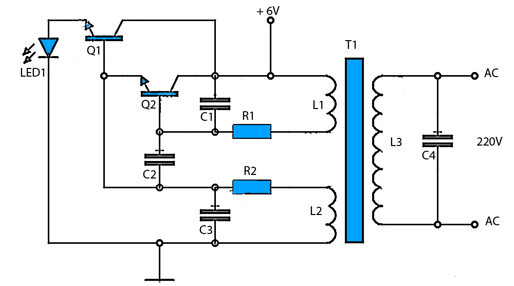
The circuit schematic presented is a voltage inverter circuit that converts a 6-volt DC input into a 220-volt AC output. It is designed to deliver a maximum output power of 30 watts and operates with a low input current....
To alleviate any concerns related to high frequency, a ready-made Aurel audio FM transmitter module has been utilized. This compact circuit board, measuring 2 cm by 4 cm, supports a modulation frequency track and delivers an RF power of...
This circuit is a modified version of a function-generator circuit. It features a battery-powered sine wave generator that can be continuously adjusted from 100 Hz to 10 kHz. The described circuit utilizes a sine wave generator to produce a continuous...
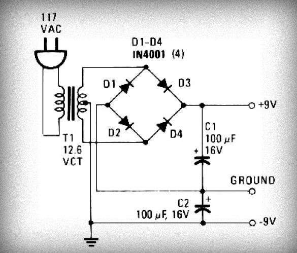
Initially, voltage from AC 220V or 110V enters the transformer, which reduces it to 12V AC. This AC voltage is then rectified using either four diodes or a bridge rectifier to convert it to DC voltage. The resulting DC...
This circuit generates an accurate and adjustable sine-wave output by removing harmonics from a square wave. This circuit utilizes a harmonic filter to transform a square wave input into a sine wave output. The primary function of this circuit is...