
Pontiac Fiero Wiring Diagram and Electrical System Schematic
The 1985 Pontiac Fiero features a complex electrical system designed to support various components and functionalities integral to vehicle operation. The wiring diagram serves as a comprehensive reference, illustrating the connections between different electrical components, including the battery, alternator, ignition system, lighting, and various sensors.
Key components of the electrical system include:
1. **Battery**: The primary power source for the vehicle, providing the necessary voltage for starting the engine and powering electrical accessories.
2. **Alternator**: Responsible for charging the battery while the engine is running, converting mechanical energy into electrical energy.
3. **Ignition System**: Comprising the ignition switch, coil, and spark plugs, this system is crucial for starting the engine and ensuring proper combustion.
4. **Lighting System**: This includes headlights, taillights, and interior lights, each with specific wiring configurations to ensure functionality and safety.
5. **Sensors**: Various sensors, such as those for the engine management system, provide critical data to the vehicle's electronic control unit (ECU) for optimal performance and fuel efficiency.
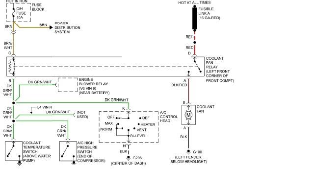
The wiring diagram includes color-coded lines representing different wire types and gauges, facilitating easy identification and troubleshooting. Each component is marked with specific codes that correspond to the vehicle's service manual, allowing technicians to diagnose issues effectively.
In summary, the 1985 Pontiac Fiero's electrical system is designed to provide reliable performance and safety features through a well-organized wiring diagram that aids in maintenance and repair activities.The following page outlines detail information and schematic of the 1985 Pontiac Fiero Wiring Diagram and Electrical System. The electrical system consists of: 🔗 External reference
Related Circuits
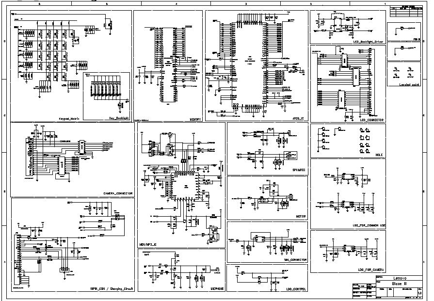
General use camera backlighting baseband circuit: the circuit includes a table of contents, Calyso, iota, matrix, keypad key, memory, IC image, LCD connector, LCD backlight driver, locate points, holes, Speaker4, camera connector, motor, MIDI/MP3 ICs, charging circuit, microphone phone,...
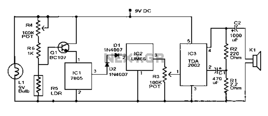
This document outlines a basic fire alarm circuit utilizing an LDR (Light Dependent Resistor) for fire detection. The circuit is designed to generate an audible alarm in response to smoke, which affects the LDR's resistance. In the absence of...
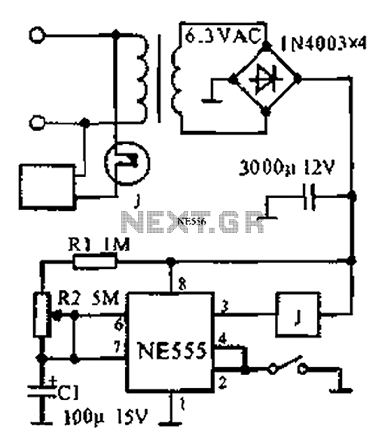
The provided information indicates that when the power supply operates between 0 to 1 hour, an AC circuit diagram is established using a 555 timer configured as a one-hour timer. The relay utilized is a J 212 IRC MR312C...
The chart illustrates a clock designed for a competition, utilizing a 555 timer circuit. This circuit is characterized by its novel design, reliable performance, ease of assembly, and engaging functionality. The 555 timer is available in two types: bipolar...
This is a remote-controlled land rover that can be operated using a cell phone. This allows the user to move the land rover by sending various commands from their device. The rover can be controlled from virtually anywhere in...
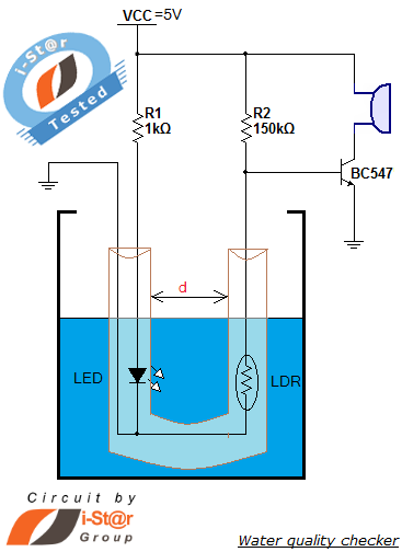
How to measure water purity and test water quality using a simple electronics project. Water purity measurement and water quality analysis can be performed using a water purity checker circuit. This circuit is constructed around a Light Dependent Resistor...