
Simple Power Supply Circuit easy to make Schematic Diagram
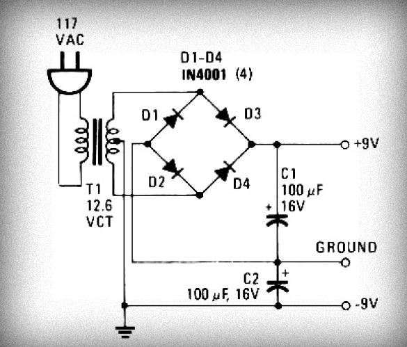
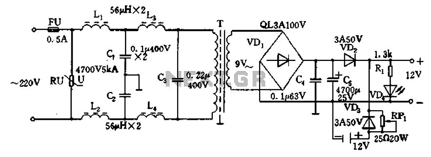
The power supply circuit described involves several key components and stages that are essential for converting high-voltage AC to a usable low-voltage DC output. The process begins with the transformer, which is a critical component that steps down the input voltage from either 220V or 110V AC to a lower voltage level of 12V AC. The transformer operates on the principle of electromagnetic induction and is designed to provide isolation and voltage conversion.
Following the transformer, the AC voltage is directed to a rectification stage. This stage can utilize either a configuration of four discrete diodes arranged in a full-wave rectifier setup or a single bridge rectifier, which combines four diodes into a single package. The rectification process converts the alternating current (AC) into direct current (DC) by allowing current to flow in only one direction. The output from this stage is pulsating DC, which still contains ripples due to the nature of the rectification process.
To smooth out these ripples and provide a more stable DC output, an electrolytic capacitor is employed. The capacitor acts as a reservoir, charging up when the voltage rises and discharging when it falls, thereby reducing voltage fluctuations. The value of the capacitor is chosen based on the load requirements and the desired level of ripple voltage.
The final output of the circuit is a DC voltage that is accessible through three terminals: the positive terminal provides the output voltage, the negative terminal serves as the return path, and the ground terminal is connected to the circuit's common reference point. This configuration allows the power supply circuit to be versatile and suitable for various electronic applications, making it an essential building block in many electronic projects.
Overall, this simple power supply circuit is not only easy to construct but also provides a reliable source of low-voltage DC power for a wide range of electronic devices and circuits.In the first, voltage from AC 220V or 110V entered to the transformer and will be lowered into 12V AC. And then AC voltage will be rectified by 4 diode or you can use bridge diode to the DC voltage. And the DC voltage output will be filtered by Condesator electrolit and the voltage output ready to use.
Its DC voltage with triple voltage (+), ( -), and ground. You are reading the Circuits of Simple Power Supply Circuit, easy to make And this circuit permalink url it is 🔗 External reference
Related Circuits
This is a simple oscillator with multiple resistors in series. When you press any switch, the circuit starts oscillating. You can use variable resistors instead of the 1k resistors. Using variable resistors, you will be able to tune the...
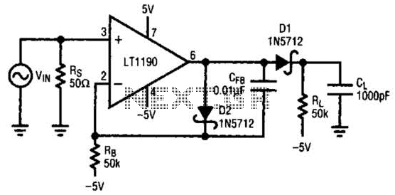
In this open-loop design, the detector diode is D1, and a level-shifting or compensating diode is D2. Load resistor RL is connected to -5 V, and an identical bias resistor RB is used to bias the compensating diode, also...
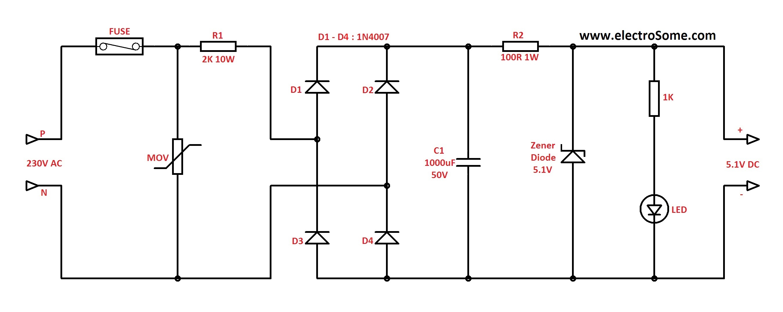
In Capacitor Power Supplies, a Voltage Dropping Capacitor is used in series with the phase line. Ordinary capacitors are unsuitable for these applications because mains spikes can create holes in the dielectric of standard capacitors, leading to failure. This...
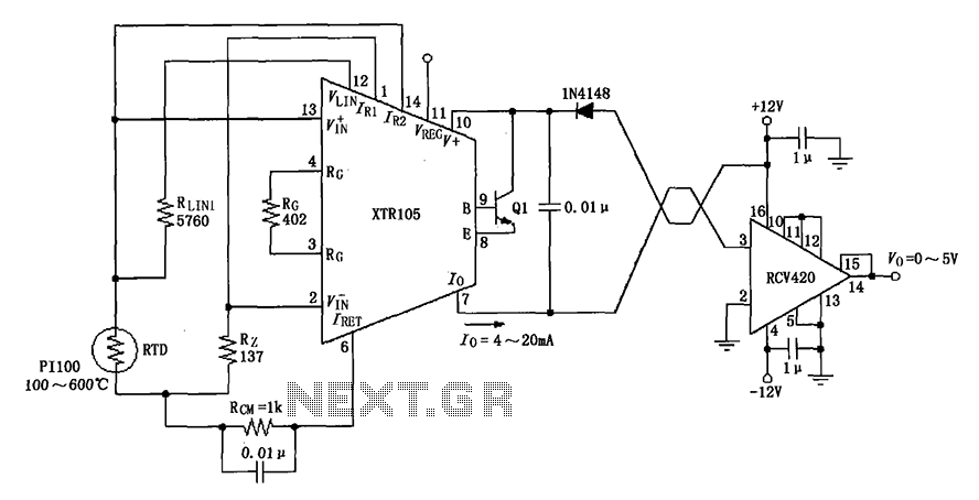
The circuit utilizes a Pt100 type resistance temperature detector (RTD). It operates within a temperature range of 100 to 600 °C, where the XTR105 outputs a current of 4 to 20 mA, and the RCV420 provides an output voltage...
12V DC power supply circuit. A typical 12V DC power supply circuit includes a transformer that converts mains voltage to the required 12V AC output. It features a full-wave rectifier and a capacitor filter. The circuit typically incorporates a...
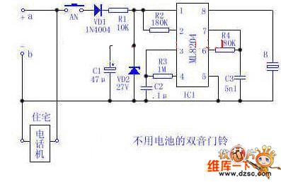
Utilize the 48V (60V) DC feedback electric current supplied by the phone feedback line as the operational energy source for the electronic doorbell, which is highly economical and practical. This document introduces a two-tone doorbell circuit that operates without...