
Thyristor controlled motor reversing circuit a timer
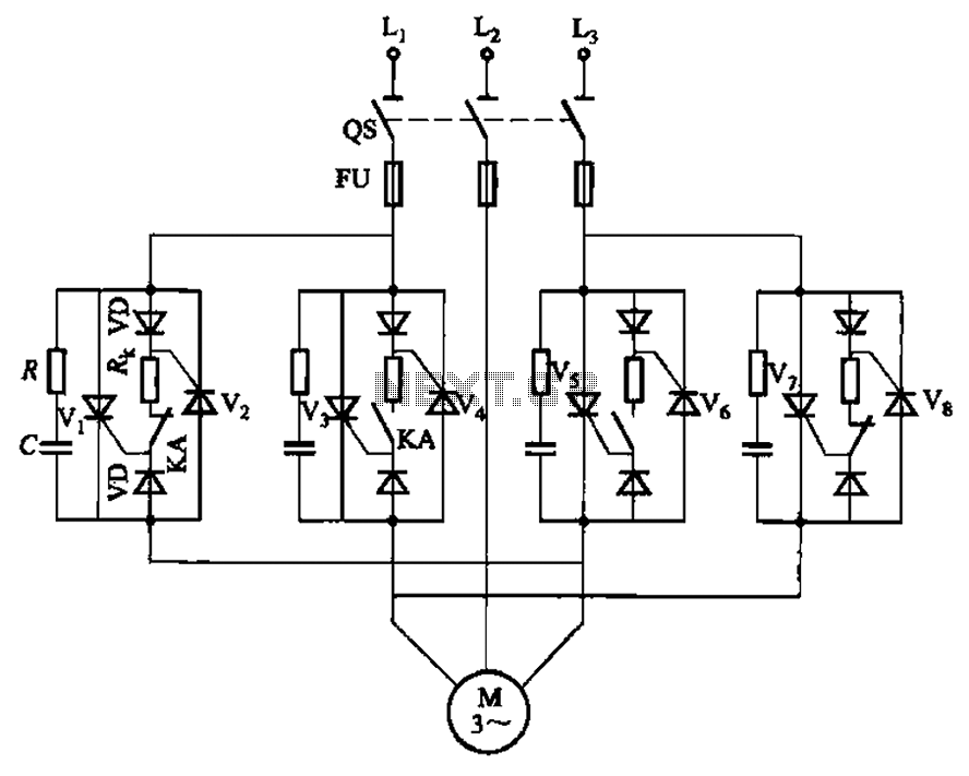
The circuit operates by utilizing a combination of thyristors and transistors to achieve precise control over the motor's operation. The thyristors V1, V2, V7, and V5 facilitate the positive rotation of the motor, enabling it to run in a forward direction. Conversely, thyristors V3, V4, and V6 manage the inversion control, allowing the motor to reverse its direction.
The role of transistor VT1 is critical as it acts as a switch that extends the timing for the motor's forward and reverse operations. This switching action is complemented by the delay circuit involving VT2, which further refines the timing control by introducing a delay before the motor changes direction. The resistors R and capacitors C serve as protective components, ensuring that the thyristors operate within safe limits and preventing potential damage due to overcurrent conditions.
Potentiometers RPi and RP2 provide an interface for users to adjust the timing settings. By varying the resistance in these potentiometers, the duration for which the motor runs in either direction can be modified, allowing for flexibility in applications where different timing requirements are necessary. This feature is particularly advantageous in automation systems where precise control over motor operations is essential for optimal performance.
Overall, this circuit exemplifies an effective design for controlling motor operations with an emphasis on timing and directional control, making it suitable for various industrial and automation applications. Circuit shown in Figure 3-69. It applies to require frequent timing control motor reversing operation of the occasion. Drawing, thyristor Vl, V2 and V7, vs used as a positive c ontrol rotation, V3, V4 and V5, V6 used inversion control; motor forward running and reverse running time, respectively, by the extension of single-junction transistor VTi and the like of the circuit configuration and the like by the VTz delay circuit to control; the resistor R and the capacitor C is used for the thyristor protection. Adjust potentiometer RPi and RPz, can change the motor running forward and reverse running time respectively.
Related Circuits
This class-D audio amplifier is suitable for TV and home stereo systems. The TDA7882 integrated circuit (IC) provides a class-D audio amplifier solution. Since this IC has a single channel output, two units are required for stereo applications. The...
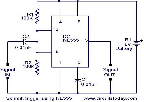
In addition to its timing functions, the two comparators of the 555 timer can be utilized independently for various applications. One such application is a Schmitt Trigger. The inputs of the two comparators (pin 2 and pin 6) are...
A milliamp meter can function as a voltmeter by incorporating a series resistance. The required resistance is calculated by dividing the full-scale voltage reading by the full-scale current of the meter movement. For instance, using a 1 milliamp meter...
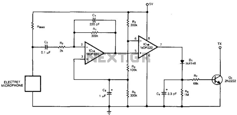
An electret microphone feeds a bandpass filter circuit (IC1A), which subsequently drives a comparator. This comparator activates Q1, a switch that conducts when audio signals from IC1B cause D1, C4, R6, and R7 to bias it ON. The circuit begins...
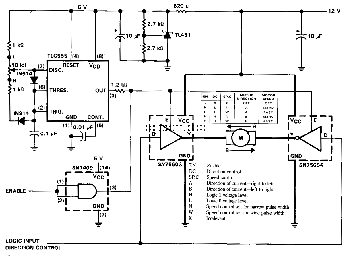
The figure illustrates a reversible DC motor drive application with adjustable speed control. The D inputs for these drivers are complementary and can be tied together and driven from the same logic control for bidirectional motor drive. The enables...
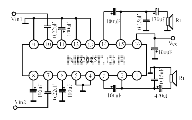
The D2025 is a dual audio power amplifier circuit designed as a stereo audio power amplifier integrated circuit. It comes in a DIP16 package and is applicable for various portable devices, such as tape recorders or portable stereo systems....