
Touch fan speed control circuit eight stalls

The circuit functions as follows: the touch sensor chip detects contact with the conductive sheet, initiating a signal that triggers the CC4011 timing pulse oscillator. This oscillator generates timing pulses that are fed into the ND gates, which perform logical operations to create a sequential output. The CC4017 counter then counts these pulses, with each output corresponding to a specific gear speed.
The outputs Y1 to Y9 are connected to a series of resistors that form a voltage divider network. The varying resistance values are essential for adjusting the output signals to the TRIAC, which controls the power delivered to the motor. By manipulating the conduction angle of the TRIAC, the circuit can effectively regulate the speed of the motor, allowing for smooth transitions between the eight different settings.
The resistors R6, R62kC1, R7, and R1a are selected based on the desired performance characteristics of the motor. These components must be fine-tuned during the debugging process to ensure that the voltage across the motor remains within the specified range of 25V to 30V, which is critical for optimal operation and to prevent potential damage to the motor or circuit components. Proper calibration of these resistors ensures the reliability and efficiency of the speed control mechanism, making it suitable for various applications requiring precise motor speed adjustments. Circuit shown in Figure 3-7. Just touch sensor chip (conductive sheet). Eight gear speed can be realized. CC4011 timing pulse oscillator consists of an integrated circuit Ai NA ND gate 1,2 composition. When touching conductive sheet M while, Ai Kai vibration that is to CC4017 ~ - into the counting/pulse divider Az issued counting pulse, the output of Yl A2 of ~ Y9 turn out high through different resistor values R ~ ~ Ria buck to the optocoupler B, and then control the TRIAC V conduction angle, to achieve eight gear speed. Resistors R6 level 62kC1, R7 ~ R1a required to determine the actual debugging, so that two adjacent block electrical pressure (voltage across the motor) the order of 25 ~ 30V.
Related Circuits
This document outlines a simple SWR (Standing Wave Ratio) protection circuit that can be easily constructed. The directional coupler and detector components are sourced from an old VHF SWR meter. It is advisable to replace the existing RF bypass...
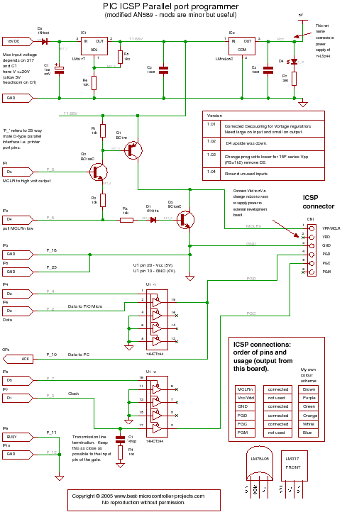
A PIC programmer circuit that operates using long cables from a PC to the programmer. The PIC programmer circuit is designed to facilitate the programming of PIC microcontrollers via a connection to a personal computer (PC) using extended cabling. This...
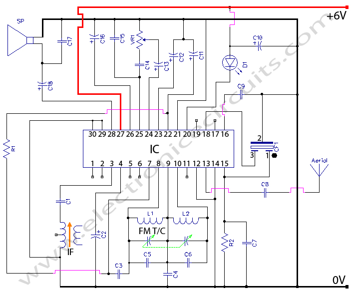
Radio Circuit Diagram Manual PDF Download. The radio circuit diagram manual provides a comprehensive guide for understanding and constructing radio circuits. It includes various circuit schematics, components specifications, and operational principles essential for both beginners and experienced engineers in the...
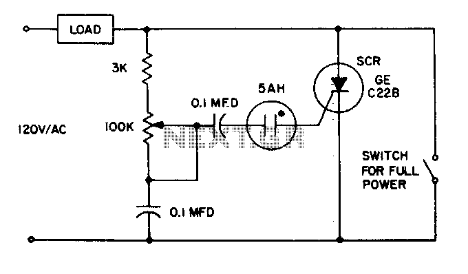
The 5AH will trigger when the voltage across the two 0 µF capacitors reaches the breakdown voltage of the lamp. Control can be obtained from full off to 95% of the half-wave RMS output voltage. Full power can be...
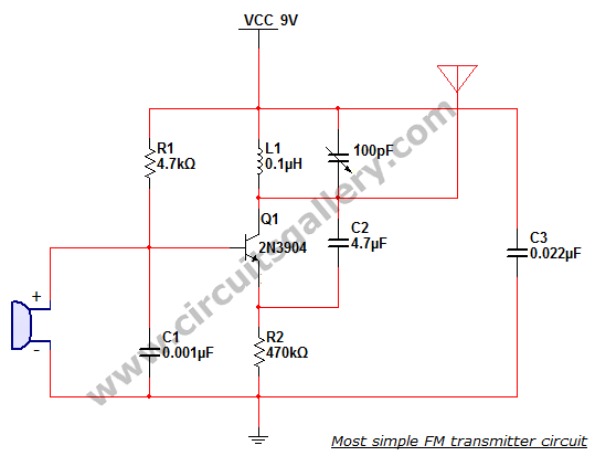
This is the simplest single transistor FM wireless transmitter circuit ever posted in CircuitsGallery. In the field of telecommunications, frequency modulation (FM) transmits information by altering the frequency of a carrier wave based on the message signal. FM utilizes...
The circuit described below is notable for its low power consumption. With a 9V input and no load at the output, it draws only 50 mA, which is significantly lower than the quiescent current of a 78L05 regulator. The...