
Most simple FM transmitter circuit diagram
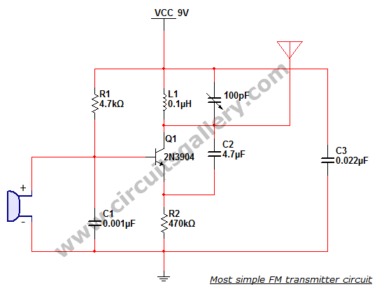
The FM wireless transmitter circuit is a fundamental project for those interested in electronics and telecommunications. It typically incorporates a few essential components: a transistor (2N3904), a condenser microphone, an inductor, a variable capacitor, and a simple copper wire antenna. The circuit operates by converting sound waves into electrical signals using the condenser microphone. The microphone's diaphragm, which reacts to sound pressure variations, produces an alternating current (AC) signal that represents the audio input.
The heart of the FM transmitter is the oscillating tank circuit formed by the inductor L1 and the variable capacitor. This tank circuit is crucial for generating the oscillations required for frequency modulation. The transistor amplifies the signal, allowing it to drive the antenna effectively. The oscillation frequency can be fine-tuned by adjusting the variable capacitor, ensuring that the transmitter operates within the desired VHF band.
The antenna, a straightforward copper wire, acts as a radiating element for the modulated signal. Its dimensions and design influence the efficiency and range of the transmission. Consequently, careful consideration of the inductor's specifications and the antenna's design parameters is essential for optimal performance.
In summary, the described FM wireless transmitter circuit serves as an excellent introduction to frequency modulation technology, offering practical insights into circuit design and assembly. It highlights the importance of component selection and configuration in achieving successful wireless transmission of audio signals.This is the most simplest and single transistor FM wireless transmitter circuit that ever posted in CircuitsGallery. In telecommunication field, frequency modulation (FM) transmits information by changing the frequency of a carrier wave according to message signal.
FM uses VHF radio frequencies usually 87. 5 108. 0 MHz to transmit and receive t he FM signals. Here I will give you theexplanations about FM transmitter, how to make a FM transmitter andhow a simple FM transmitter is designed and assembled etc. The performance and working of a wireless audio transmitter circuit mainly depends on inductor coil specification and the value of variable capacitor.
Even a slight change of inductance or capacitor can shift the harmonic frequency from the VHF (88-108 MHz) band. This article will enable you to answer how to build an FM radio transmitter . Also you will get the confidence tobuild your own FM transmitter. A condenser microphone is used to accept the sound signals. Inside the mic, a capacitive sensor diaphragm is present. It vibrates according to the air pressure changes and generates AC signals. The inductor L1 and variable capacitor (trimmer) forms an oscillating tank circuit along with the transistor 2N3904.
It is the common NPN transistor used for general purpose amplifications. As long as the current exists across the inductor coil L1 and the variable capacitor, the tank circuit will oscillate at the resonant carrier frequency for FM modulation. Capacitor C2 acts as a negative feedback to the oscillating tank circuit. Every FM transmitter circuit requires an oscillator part to generate the radio Frequency (RF) carrier waves.
The name Tank` circuit is derived from the capacity of the LC circuit to store energy for oscillations. The modulated signal from the antenna is radiated as radio waves at FM frequency band. Antenna is nothing but a simple copper wire of 20 cm long and 24 gauge. The length, inner diameter, number of turns etc. are the important factors to be considered while inductor designing. You can design inductor using the following formula, 🔗 External reference
Related Circuits
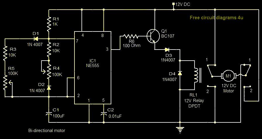
This circuit illustrates a bi-directional motor control circuit utilizing the NE555 integrated circuit (IC). Features include a 12V DC power supply, with the IC employed to control relay RL1. The bi-directional motor control circuit designed with the NE555 IC allows...
When the unit is positioned near a live conductor, whether insulated or buried in plaster, capacitive coupling occurs between the live conductor and the probe. This interaction activates the counter, resulting in the LED flashing five times per second,...
The bearing fault detector circuit consists of a bearing detection sensor, a signal processing circuit, a transistor (V), an audio amplifier integrated circuit (IC2), a speaker (BL), an RC element, an integrated circuit (IC1), and a light-emitting diode (VL)....
Pressing the pushbutton on the transmitter activates a sound and/or light alert in the receiver. This system operates without wiring or radio frequencies; instead, the transmitted signal is conveyed through the mains supply line. It is suitable for use...
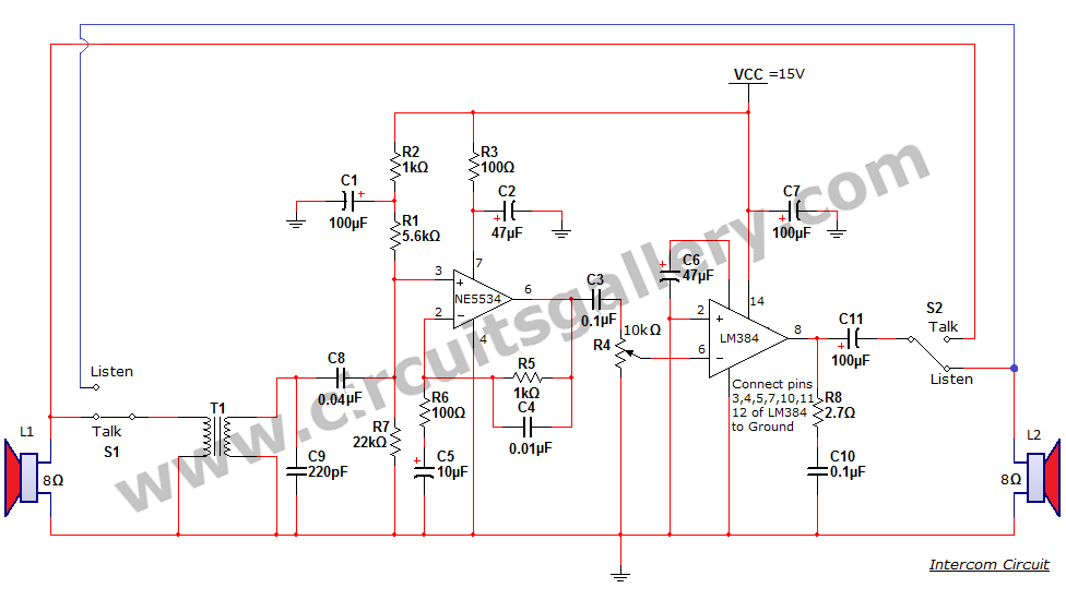
An intercom or intercommunication circuit is a two-way communication system that provides a reliable communication line and is easy to implement. The circuit consists of an amplifier, two switches, and two loudspeakers, allowing for the extension of the system...

A schematic diagram is a layout of symbols and connections representing every electronic component in a circuit, serving as a guide to understanding how the circuit functions. Learning to read these diagrams may initially seem challenging, but it is...