
Intermittent start and stop cycle control circuit Five of a
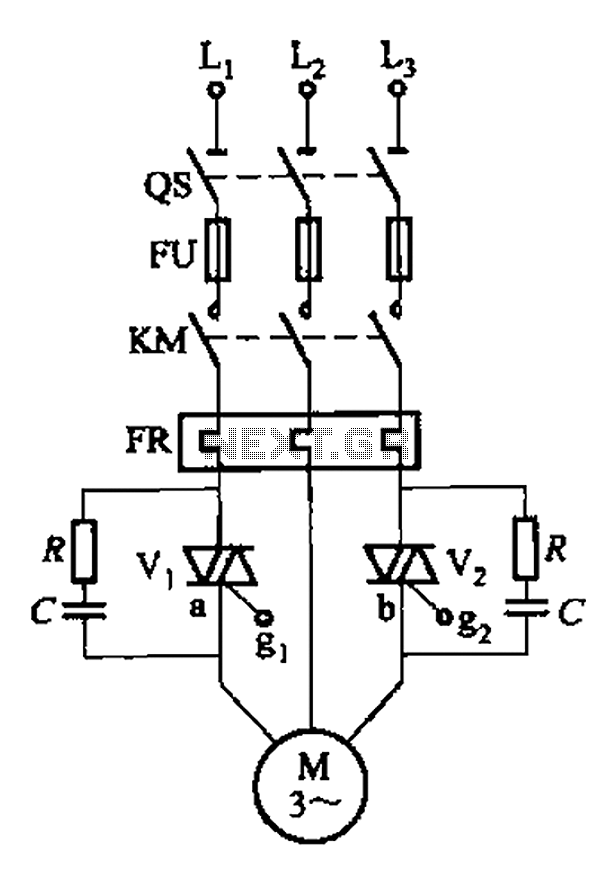
The circuit operates using a transistor multivibrator configuration, which is designed to generate oscillations. This type of circuit typically consists of two transistors that alternately switch on and off, creating a square wave output. The coupling between the two branches is achieved through capacitive and resistive elements, forming an RC timing circuit that influences the frequency of oscillation.
The inclusion of the RPi adjustment potentiometer provides a means to fine-tune the timing characteristics of the circuit. By adjusting this potentiometer, the user can modify the charge and discharge times of the timing capacitors, thereby controlling the duration of the output pulse. This feature is particularly useful for applications where precise motor control is required, allowing for adjustments to be made while the motor is in operation.
The RP2 component also plays a critical role in the timing adjustments, serving as an additional variable resistor that can be configured to alter the resistance in the timing circuit. This flexibility ensures that the multivibrator can be tailored to meet specific operational requirements, enhancing the overall functionality of the system.
In summary, the circuit in Figure 3-80 exemplifies a versatile multivibrator design that integrates timing control through adjustable components, making it suitable for various applications where motor speed and operation timing are crucial. Circuit shown in Figure 3-80. Which controls part of the transistor multivibrator. Multivibrator is a strong positive and negative feed-forward amplifier, its two branches are coupled RC timing circuit, so there is no steady state. RPi adjustment potentiometer and RP2. You can change each time the motor is running and stop time.
Related Circuits

The pressure transmitter circuit data acquisition system utilizes the 1B31, an 18-bit A/D converter (AD1170), and an MCS-51 microcontroller. The configuration, as depicted in the accompanying diagram, features a full-scale output voltage of 10 mV from the pressure transmitter...
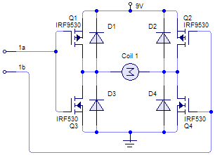
General Diagram of Motor Controller Manual PDF Download. The motor controller is an essential component in various applications, including robotics, electric vehicles, and industrial machinery. It regulates the operation of electric motors by controlling parameters such as speed, direction, and...
An efficient 4-stage stabilized power supply unit is designed for testing electronic circuits. This unit provides well-regulated and stabilized output, which is essential for most electronic circuits to yield accurate results. The circuit features audio-visual indicators to signal a...
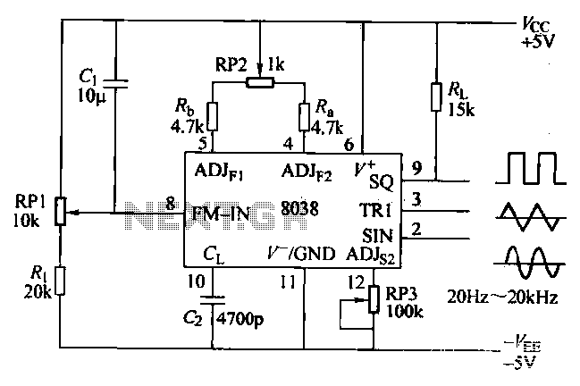
The ICL8038 function generator is an audio composition device that utilizes the ICL8038 integrated circuit. The resistance Ri potentiometer RP1 is used to determine the flow potential. Typically, the output is set to approximately 2Vcc / 3. Lowering the...
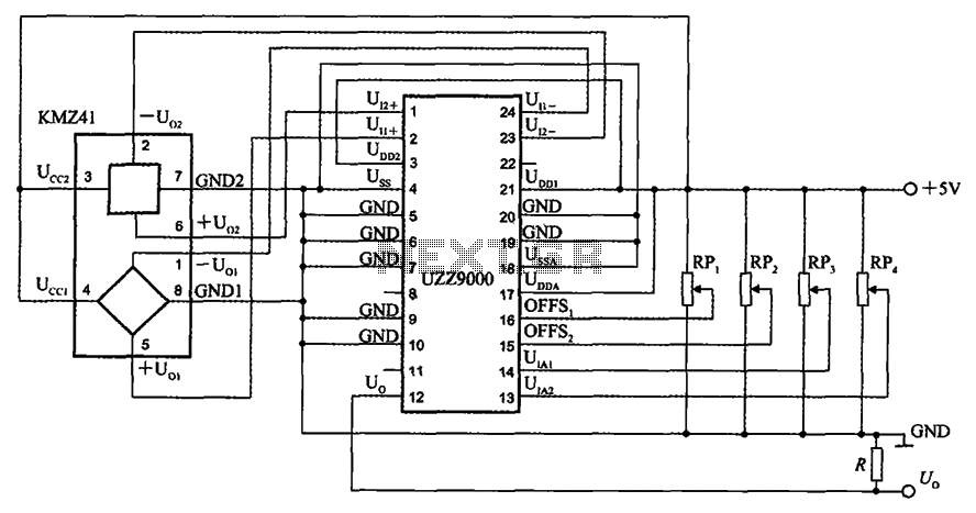
The UZZ9000 KMZ41 detection circuit is configured based on the voltage output type and angle. It operates with a +5V power supply. Potentiometers RP1 and RP2 are used for offset voltage adjustment, while potentiometers RP3 and RP4 are utilized...

The device is referred to as the Itsy Bitsy USB Lamp. This concept is remarkably straightforward, raising the question of why it had not been conceived earlier. Originating as a student project at Massey University in Wellington, New Zealand,...