
Pressure Transmitter Data Acquisition System circuit 1B31,18 bit A / D converter AD1170 and MCS-51 microcontroller

The pressure transmitter circuit is designed to accurately capture and process pressure data through a systematic approach involving both hardware and software components. The 1B31 amplifier is configured to amplify the small signal from the pressure transmitter, ensuring that it is within the operational range of the A/D converter. The gain setting of 500 is critical as it allows for the full-scale output voltage of the transmitter, which is only 10 mV, to be effectively scaled to a 0-5 V range suitable for digital processing.
The AD1170 A/D converter is a pivotal element in this system, providing high-resolution data acquisition with its 18-bit resolution. The initialization command ECAL serves a dual purpose: it not only sets the reference voltage for accurate readings but also ensures that the system can adapt to any variations in the reference voltage over time. This adaptability is crucial for maintaining measurement integrity in varying operational conditions.
The microcontroller, based on the MCS-51 architecture, plays an essential role in managing the data acquisition process. It handles the initialization of the AD1170, processes the incoming digital signals, and performs necessary computations to derive meaningful pressure measurements. The inclusion of a low-pass filter in the design aids in reducing noise and enhancing the signal-to-noise ratio, which is vital for applications requiring precise measurements.
Furthermore, the system's design minimizes the effects of fixed offset voltages that can arise from the bridge's asymmetry, thereby improving accuracy without the need for manual calibration adjustments via a zero potentiometer. This feature simplifies the setup and maintenance of the system, making it more user-friendly and reliable in practical applications. Overall, this pressure transmitter circuit represents a robust solution for high-accuracy pressure measurement and data acquisition in various industrial and research settings.Pressure transmitter circuit data acquisition system by 1B31,18 bit A / D converter AD1170 and MCS-51 microcontroller configuration shown in Fig. Will be a full-scale output voltage of 10mV pressure transmitter connected to the 1B31, 1B31 set a gain of 500 times, the output voltage range is 0 ~ 5V. Excitation voltage is set to + 5V, in order to perform computing the ratio, the AD1170 voltage also serves as a reference voltage by the voltage of the initialization command ECAL as AD1170 full-scale input voltage, then by periodically calibrating the A / D converter You can follow the reference voltage changes, with the ratio of output characteristics.
As a result of the low-pass filter and A / D conversion technology, so the system has a high common-mode rejection ratio. Use microcontroller AD1170 is initialized, but also to eliminate fixed offset voltage generated by the bridge asymmetric, so do not have to use zero potentiometer (or software) zeroing up.
Related Circuits
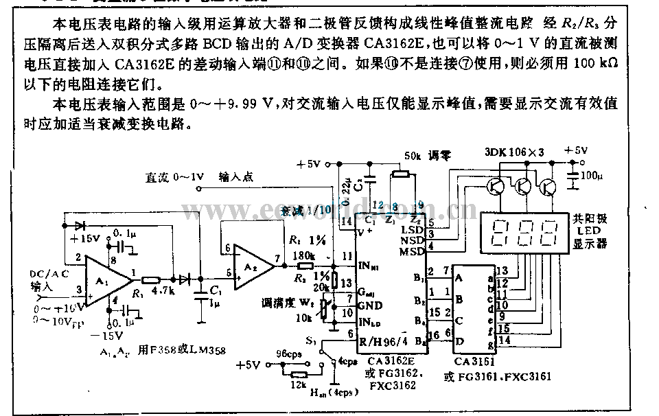
The input stage of this voltmeter circuit utilizes an operational amplifier and diode feedback to create a linear peak value rectifier circuit. A partial pressure isolation through resistors R1 and R2 directs the signal to a dual multi-channel BCD...
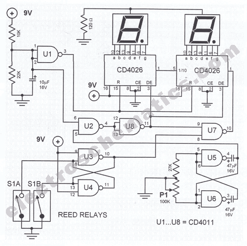
This digital DIY tachometer for bicycles utilizes two reed switches to gather speed information. The reed switches are positioned near the wheel rim, where permanent magnets are mounted on the wheel spokes. As the spokes rotate, the magnets pass...
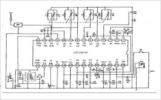
The CXA1600M and CXA1600P are 8-pin single-chip bipolar integrated circuits (ICs) designed for AM radios. These ICs encompass all necessary functions from the front-end to the power amplifier, eliminating the need for external filters, which makes the attachment of...
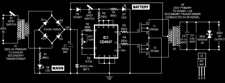
This circuit diagram of a UPS is designed for use with cordless telephones that cannot operate during a power failure. Since the UPS is intended solely for telephones, its output power is limited to 1.5W. This UPS circuit is...
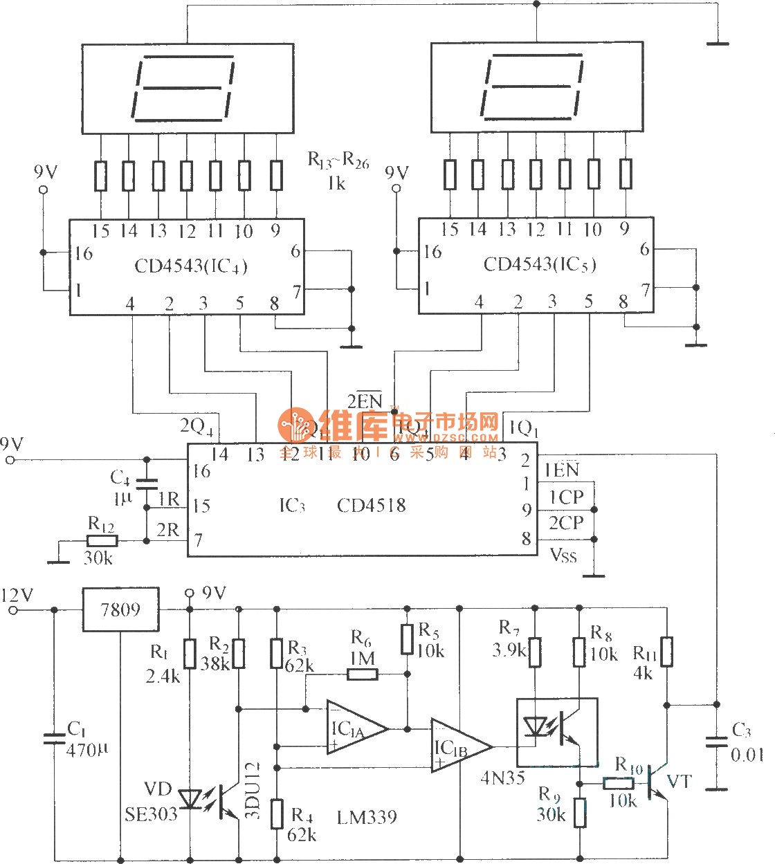
The circuit includes an optical input circuit (VD, 3DU12), a pulse forming circuit (IC1A, IC1B functioning as a voltage comparator; optical coupler; transistor switching circuit), and a counting and display circuit. The circuit architecture consists of several key components that...
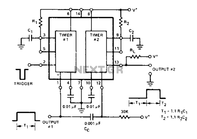
The Dual Timer Exar XR-2556 features a timing mechanism that can be triggered through capacitive coupling on a secondary timing pin. When a trigger input is engaged, the duration T1 can be set to 1.1R1C1, resulting in an increased...