Stablised Power Supply With Short Circuit Indication
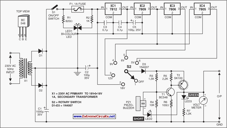
An efficient 4-stage stabilized power supply unit is designed for testing electronic circuits. This unit provides well-regulated and stabilized output, which is essential for most electronic circuits to yield accurate results. The circuit features audio-visual indicators to signal a short circuit in the PCB under test, allowing for immediate power cut-off to protect valuable components from damage. It offers four different regulated outputs of 12V, 9V, 6V, and 5V, along with an unregulated 18V output, selectable via a rotary switch (S2). The selected output is displayed on an analog voltmeter connected to the output rails. A standard 18V-0-18V, 500mA step-down transformer is utilized to generate 18V AC. Diodes D1 and D2 form a rectifier to convert this to 18V DC, which is smoothed by capacitor C1 before being fed into a set of regulator ICs (IC1 through IC4). These regulators produce fixed, regulated outputs of 12V, 9V, 6V, and 5V, respectively, connected to the rotary switch contacts. The power supply is capable of supporting loads requiring up to 200mA current. Complementary transistors T1 and T2 activate when power is applied to the circuit. The full selected supply voltage is available at the collector of transistor T2, which powers the load. LED3 indicates the presence of output voltage. The negative terminal of piezo-buzzer PZ1 is linked to the output rail through LED2, keeping the buzzer silent while the negative terminal is at full supply voltage. In the event of a short circuit at the output, LED2 illuminates, activating the piezo-buzzer. A fuse-failure indicator distinguishes between output short circuits and input failures, comprising a bicolor LED (LED1) and resistors R1 and R2. When power is present and the fuse is intact, both halves of LED1 illuminate in parallel to emit a yellowish light. If the fuse fails, the green LED turns off while the red LED lights up to signal fuse failure. The circuit can be easily assembled on a general-purpose PCB, with small heat sinks recommended for all ICs to dissipate heat. The output voltage can be monitored using a voltmeter, and the entire assembly should be enclosed in a metal box with provisions for the voltmeter, LEDs, rotary switch, and other components.
This 4-stage stabilized power supply unit is designed to provide reliable and adjustable voltage outputs for various electronic testing applications. The use of a step-down transformer ensures efficient conversion of mains voltage to a manageable level, while the rectification and smoothing stages provide a stable DC voltage. The integration of multiple regulator ICs allows for versatility in output voltage selection, catering to different circuit requirements.
The audio-visual short circuit detection mechanism enhances the safety of the testing process, providing immediate feedback and protection against component damage. The complementary transistors T1 and T2 play a crucial role in managing the power distribution to the load, ensuring that the selected voltage is consistently delivered. The visual indicators, such as LED3 for output voltage presence and the bicolor LED for fuse status, contribute to user-friendly operation and monitoring.
The design is suitable for assembly on a standard PCB, making it accessible for hobbyists and professionals alike. The recommendation for heat sinks is vital, as it ensures the longevity and reliability of the regulator ICs under load conditions. Enclosing the circuit in a metal box not only provides physical protection but also minimizes electromagnetic interference, enhancing the overall performance of the power supply unit. This comprehensive design makes it an invaluable tool for testing and troubleshooting electronic circuits.Here is an efficient 4-stage stabilised power supply unit for testing electronic circuits. It provides well regulated and stabilised output, which is essential for most electronic circuits to give proper results. The circuit provides an audio-visual indication if there is a short circuit in the PCB under test, so the power supply to the circuit un
der test` can be cut-off immediately to save the valuable components from damage. The circuit provides four different regulated outputs (12V, 9V, 6V and 5V) and an unregulated 18V output, which are selectable through rotary switch S2. The selected output is indicated on the analogue voltmeter connected to the outputs rails. The circuit uses a standard 18V-0-18V, 500mA step-down transformer to generate 18V AC. A rectifier diode comprising diodes D1 and D2 provides 18V DC, which is smoothed by capacitor C1 and given to the combination of regulator ICs (IC1 through IC4).
The regulator ICs produce fixed, regulated outputs of 12V, 9V, 6V and 5V, respectively, which are connected to the rotary switch contacts. This power supply is useful for loads requiring up to 200mA current. Complementary transistors T1 and T2 conduct when the power to the circuit is switched on. Full selected supply voltage is available at the collector of transistor T2, which is used to power the load.
LED3 indicates the presence of output voltage. The negative terminal of piezo-buzzer PZ1 is connected to the output rail via LED2, so the piezo-buzzer remains silent as its negative terminal is also at full supply voltage (selected). If there is a short circuit at the output, LED2 glows to activate the piezo-buzzer. A fuse-failure indicator distinguishes short circuit at the output and input failure. It consists of a bicolour LED (LED1) and resistors R1 and R2. When power is available and the fuse is intact, red and green halves of LED1 are effectively in parallel to output a yellowish light.
When fuse fails, green LED goes off and red LED lights up to indicate fuse breakdown. The circuit can be easily constructed on a general-purpose PCB. Use small heat-sinks for all ICs to dissipate heat. The output voltage can be read on a voltmeter. Enclose the circuit in a metal box with provisions for voltmeter, LEDs, rotary switch, etc. 🔗 External reference
