
Infrared Remote Control
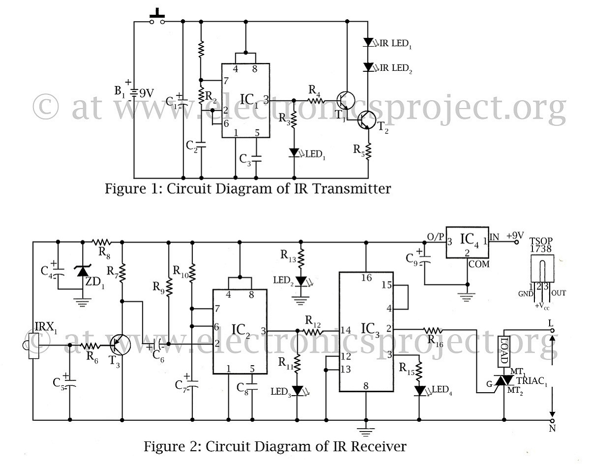
The infrared remote-controlled switch operates using a 555 timer integrated circuit (IC), which is configured in a monostable mode. This allows the circuit to be triggered by an infrared (IR) signal emitted from a compatible remote control. The primary function of the switch is to control an electrical load, such as a lamp or a fan, remotely.
The circuit consists of several key components: the 555 timer IC, an IR receiver module, a transistor, a relay, and associated passive components like resistors and capacitors. The IR receiver module detects the IR signals from the remote control and converts them into an electrical signal. This signal is fed into the trigger pin of the 555 timer.
When the 555 timer is triggered, it generates a high output signal for a predetermined duration, which can be set by adjusting the resistor and capacitor values connected to the timer. The output from the 555 timer is used to drive a transistor, which in turn activates a relay. The relay acts as a switch, controlling the power to the connected load.
The design allows for flexibility in controlling different types of loads, as long as they fall within the relay's specifications. The circuit is suitable for various applications, such as home automation systems, where convenience and remote operation are desired.
In summary, this infrared remote-controlled switch project highlights the integration of a 555 timer IC with an IR receiver to create a simple yet effective remote control mechanism for managing electrical devices.infrared remote controlled switch is second remote controlled project in this website using 555 ic circuit diagram with description of remote controlled switch. 🔗 External reference
Related Circuits
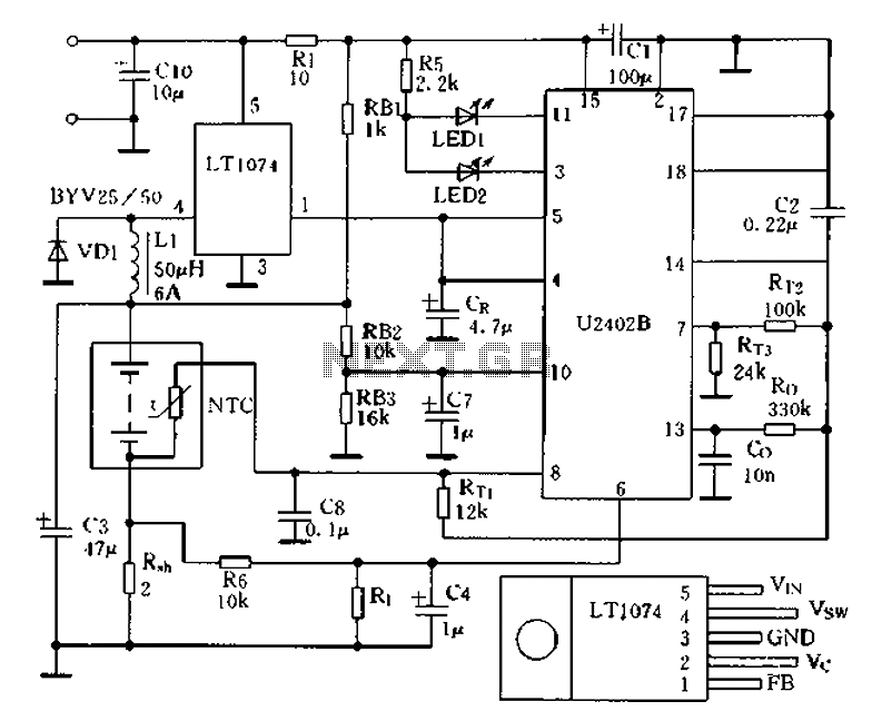
Charging circuit from the DC power supply switching power supply control The charging circuit described is designed to operate with a DC power supply, utilizing a switching power supply control mechanism. This type of circuit is commonly employed in applications...
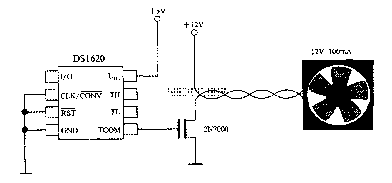
The DS1620, in conjunction with a microprocessor, is utilized to monitor temperature. By controlling the fan, the thermal conditions of the chip can be adjusted to establish a temperature control circuit as illustrated in the accompanying figure. The system...
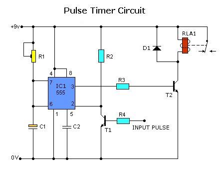
Today, solutions are offered for a timed control relay that utilizes Normally Open (NO) and Normally Closed (NC) contacts to manage the operation of other devices, enabling or disabling them as needed. The functionality of this circuit is based...
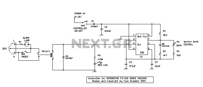
When the power is connected to the circuit by turning on SW2, RELAY1 gets energized for the time it takes to load C3 through R1 and R3. After that, the relay gets de-energized, and C3 gets discharged through R2...
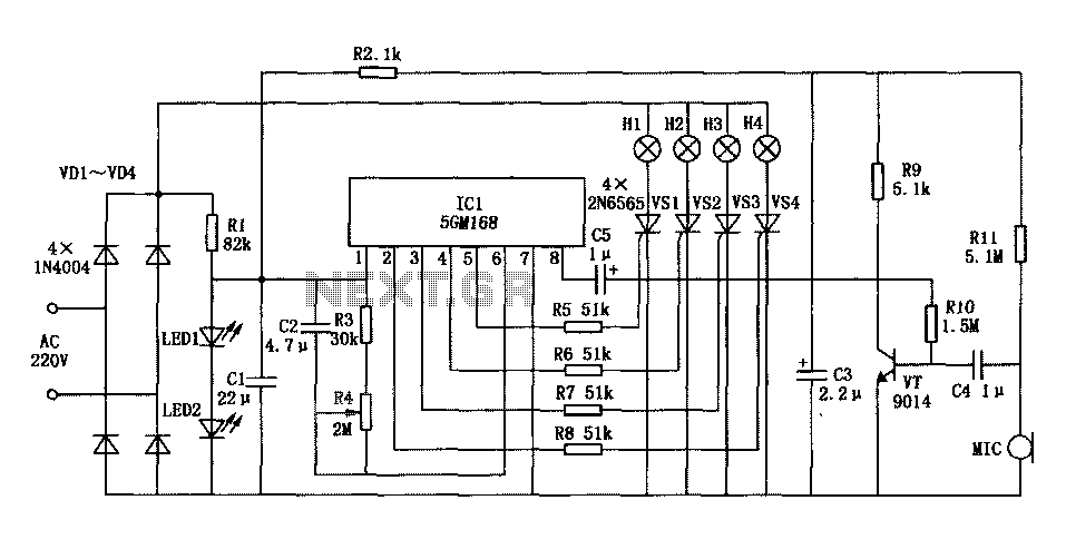
Family karaoke lighting design incorporates various methods for circuit control. The control circuit described here features a four-way light output with loop jumping and speed control capabilities. A microphone detects the acoustic signal strength, allowing the lights to jump...
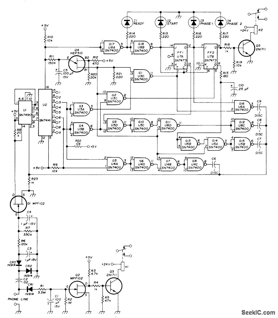
A repeater or other unattended equipment can be activated or deactivated using a standard telephone. The process involves calling the remote station, allowing it to ring three times, hanging up, waiting for 20 seconds, redialing the number, and letting...