
Five pairs of fluorescent tubes emergency circuits

The 786A multi-functional double-tube fluorescent emergency circuit is designed to provide illumination during power outages or emergencies. It utilizes two fluorescent tubes to deliver bright, energy-efficient lighting. The circuit operates by switching between normal and emergency modes, ensuring that the fluorescent tubes remain illuminated even when the main power supply fails.
In normal operation, the circuit draws power from the mains supply, allowing the fluorescent tubes to function as standard lighting. During a power outage, the circuit automatically transitions to emergency mode, drawing power from an internal battery or backup power source. This seamless switch is facilitated by a relay or solid-state switch that detects the loss of mains power.
Key components of the circuit include a battery charger, which maintains the charge of the backup battery during normal operation, and a control circuit that manages the transition between modes. The circuit may also incorporate a low-voltage disconnect feature to prevent battery over-discharge, ensuring the battery remains functional for future emergencies.
The design of the circuit emphasizes safety and reliability, with provisions for thermal management to prevent overheating of components. Additionally, the use of double tubes increases redundancy, allowing for continued operation even if one tube fails. Overall, the 786A circuit is an effective solution for emergency lighting needs in various settings, including residential, commercial, and industrial environments.786A multi-functional double-tube fluorescent emergency circuit shown in Figure 2-129. This circuit is similar to Figure 2-125.
Related Circuits
The most effective way to understand space-charge tubes is to examine actual circuits. Review the online circuits provided below, and check if any older print articles are available from friends or personal collections. After familiarizing yourself with the material,...

The following circuit illustrates a VHF pre-amplifier circuit diagram. This circuit utilizes the BFS17 transistor. Features: designed for VHF applications. The VHF pre-amplifier circuit is essential for enhancing weak radio frequency signals in the VHF (Very High Frequency) range, typically...
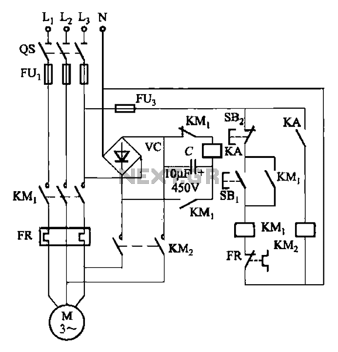
The circuit depicted in Figure 3-137 eliminates the need for a step-down transformer by utilizing the principle of energy storage capacitor discharge for braking. It can be employed to transform the power of motors with a rating of less...

Crystal oscillator integrated circuits, specifically two diagrams of oscillator circuits with oscillation frequencies of 10 MHz and 20 MHz. Crystal oscillators are essential components in various electronic applications, providing stable frequency references for timing and synchronization purposes. The circuits presented...
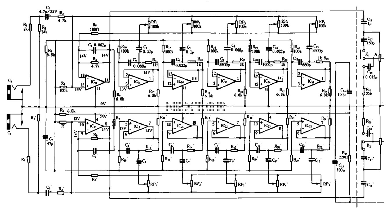
Figure 1-98 illustrates a double five-band equalizer circuit featuring a secondary connection. In this configuration, IC1 and IC14 serve as voltage amplifiers for each channel of the equalizer. The circuit also includes IC11, IC24, IC2, IC34, IC31, IC12, IC23,...

The PT2399 digital echo circuit schematic is an electronic design that utilizes the PT2399 integrated circuit (IC) for audio applications. This digital echo processor, based on CMOS technology, incorporates both analog-to-digital conversion (ADC) and digital-to-analog conversion (DAC) processes for...