
Fans of natural wind simulator circuit 2

The circuit utilizes the MOC3061, a phototransistor optoisolator, which serves as an interface between the control signal and the fan operation system. The MOC3061 is designed to provide electrical isolation, ensuring that the control circuit does not interfere with the fan's power circuit. This is particularly important in applications where the fan operates at high voltages or currents, as it protects sensitive components in the control circuit from potential damage.
In this configuration, the input side of the MOC3061 is connected to a control signal, which could be generated by a microcontroller or a manual switch. When the control signal is activated, the internal LED of the MOC3061 emits light, which is detected by the phototransistor on the output side. This triggers the phototransistor to conduct, allowing current to flow through the fan's circuit, thus turning the fan on.
The zero-off feature indicates that the circuit is designed to maintain the fan operation at zero voltage, enhancing energy efficiency and reducing unnecessary power consumption when the fan is not needed. The use of a zero-crossing detection mechanism ensures that the fan is activated at the optimal point in the AC waveform, minimizing electrical noise and potential interference with other devices.
Overall, the circuit design emphasizes safety, efficiency, and reliable operation, making it suitable for various applications where fan control is required. The integration of the MOC3061 allows for seamless control while maintaining electrical isolation between the control and power circuits. Circuit shown in Figure 3-9. It is similar to Figure 3-8, except that zero off MOC3061 type photoelectric coupling B directly connected to control fan operation.
Related Circuits
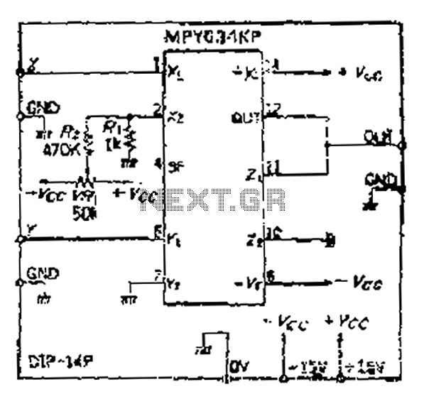
Although the inputs are differential, the right amplifier has a bias current greater than 800 nA. Therefore, the input coupling capacitor should be considered. It is important to note that the resistance value on the input side should also...
The IR Jammer is a fun project that provides a bit of safe, non-destructive fun. The Infrared Remote Control Jammer allows you to render all IR remote controls inoperative! The microcontroller in this design allows for all 6 of...
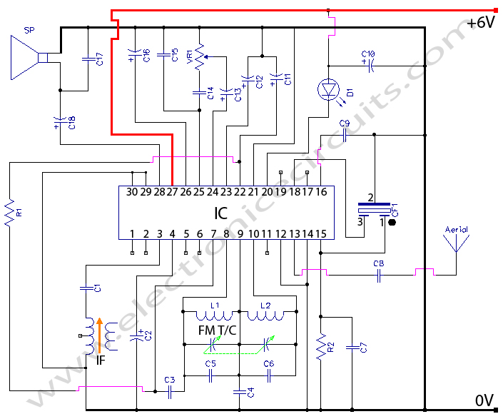
Radio Circuit Diagram Manual PDF Download. The radio circuit diagram manual provides a comprehensive guide for understanding and constructing radio circuits. It includes various circuit schematics, components specifications, and operational principles essential for both beginners and experienced engineers in the...
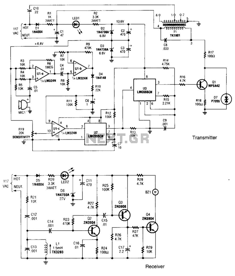
The transmitter operates by deriving its power directly from the AC line. The DC power required for the circuit is generated in two stages: the first stage powers the RF power amplifier, while the second stage supplies power to...

The LM2876 audio power amplifier circuit can be designed as a simple, high-efficiency audio amplifier capable of delivering 40W of continuous average power to an 8-ohm load with a total harmonic distortion plus noise (THD+N) of 0.1% from 20Hz...
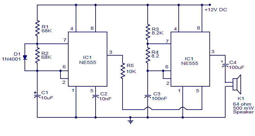
A variety of electronic circuits utilize the NE555 timer integrated circuit (IC). The circuit diagram presented illustrates a police siren based on two NE555 timer ICs, both configured as astable multivibrators. The circuit operates on a DC voltage supply...