
ne555 police siren circuit
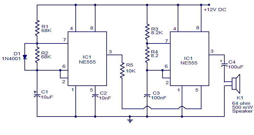
The described police siren circuit employs two NE555 timer ICs to generate a distinctive sound pattern reminiscent of an emergency vehicle siren. The first timer, IC1, is set up as a slow astable multivibrator, oscillating at a frequency of about 20Hz. This frequency is characterized by a 50% duty cycle, meaning the output signal is high for half the period and low for the other half. The output from IC1 serves as a control signal for the second timer, IC2.
IC2 is configured to operate at a much higher frequency of approximately 600Hz. This higher frequency produces a rapid pulsing sound, which is essential for achieving the siren effect. By connecting the output of IC1 to pin 5 (the control voltage input) of IC2, the oscillation frequency of IC2 is modulated. As IC1's output varies, it influences the behavior of IC2, allowing the siren sound to rise and fall in pitch, which is a critical feature of a typical police siren.
The power supply for this circuit can range from 6 to 15 volts DC, making it versatile for different applications. To further enhance the loudness of the output, a power amplifier can be connected to the output of IC2. This addition amplifies the sound produced, making it suitable for use in various scenarios where a loud siren sound is necessary.
In summary, this circuit design effectively utilizes the NE555 timer IC in a dual configuration to create a police siren sound, with the ability to adjust volume through external amplification. The interaction between the two astable multivibrators enables a dynamic output that simulates the auditory characteristics of emergency vehicle sirens.A lot of electronic circuits using NE555 timer IC Here is the circuit diagram of a police siren based on NE55 timer IC. The circuit uses two NE555 timers ICs and every of them are wired as astable multivibrators. The circuit will be powered from something between 6 to 15V DC and is fairly loud. By connecting an extra power amplifier at the output you can further increase the loudness. IC1 is wired as a slow astable multivibrator operating at around 20Hz @ 500th duty cycle and IC2 is wired as quick astable multivibrator operating at around 600Hz. The output of first astable mutivibrator is connected to the control voltage input (pin5) of IC2. This makes the output of IC2 modulated by the output frequency of IC1, giving a siren effect. In easy words, the output frequency of IC2 is controlled by the output of IC1. 🔗 External reference
Related Circuits

Right- and left-channel signals pass through buffer amplifiers C4-a and C4-b into the active crossover IG5. Low frequencies are directed to mixer IC6-c, while middle and high frequencies are sent to analog delay lines 1C1 and 1C2. The output...
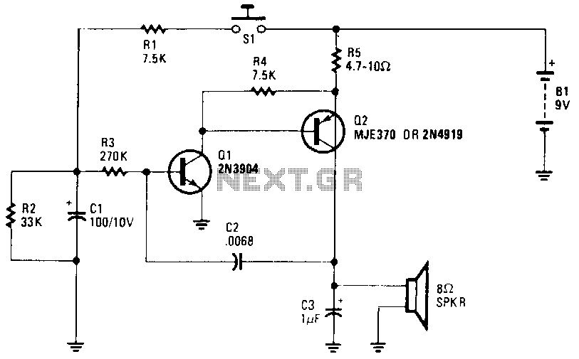
The wailing sound of a siren is generated by a voltage-controlled oscillator (VCO) comprised of transistors Q1 and Q2. Capacitor C2 provides the necessary feedback for the oscillator operation. The oscillator frequency is adjusted by the voltage applied to...
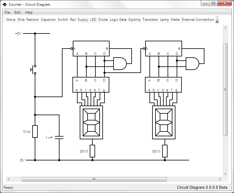
This is Circuit Diagram 0.1 Alpha Software, available for free download and open source. The Circuit Diagram 0.1 Alpha Software is designed as an intuitive platform for creating and editing electronic circuit schematics. It provides users with a variety of...
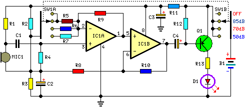
This circuit is designed to indicate, via a flashing LED, when room noise exceeds a predetermined threshold, selectable from three fixed levels: 50 dB, 70 dB, and 85 dB. The circuit utilizes two operational amplifiers to amplify the sound...
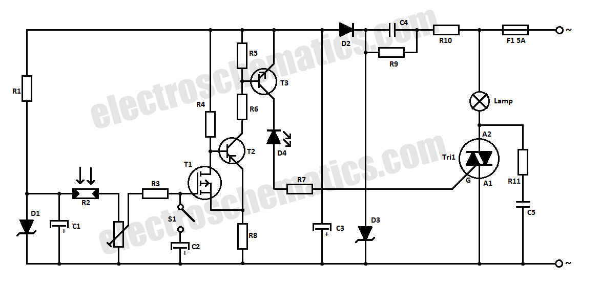
This halogen switch circuit utilizes a FET transistor, as the current is influenced by the gate voltage of the FET. The maximum gate voltage is 12V, making the circuit suitable for 12-volt lamps. The resistor R1 has a value...
The purpose of this circuit is to power a lamp or other appliance for a specified duration (30 minutes in this case) and then automatically turn it off. This functionality is particularly useful for reading in bed at night,...