
Overheat protection system consisting of circuit diagram MIC2951
The thermal protection circuit employing the MIC2951 is designed to monitor and regulate temperature within a specified range. The MIC2951 is a low-dropout voltage regulator that can be configured to provide a stable output voltage while also incorporating thermal protection features.
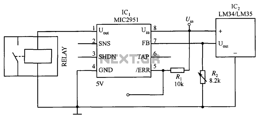
In this circuit, the key component is the MIC2951, which operates by comparing the output voltage to a reference voltage. When the temperature exceeds the set threshold, determined by the value of resistor R2, the circuit activates a protective mechanism. This can involve cutting off power to the load or triggering an alarm system to indicate an over-temperature condition.
The adjustment of R2 allows for flexibility in setting the desired temperature threshold. By changing the resistance value, the temperature at which the circuit activates can be fine-tuned to suit specific applications. This feature is particularly useful in environments where temperature fluctuations may occur, ensuring that sensitive electronic components are safeguarded against overheating.
Additional components that may be included in the schematic could consist of capacitors for stability, diodes for reverse polarity protection, and transistors for switching applications. The layout of the circuit should ensure minimal interference and optimal thermal management to enhance the performance of the MIC2951 and improve the overall reliability of the thermal protection system. Circuit shown in Figure is the use of thermal protection system consisting of circuit MIC2951. The circuit is set by adjusting the temperature threshold R2.
Related Circuits
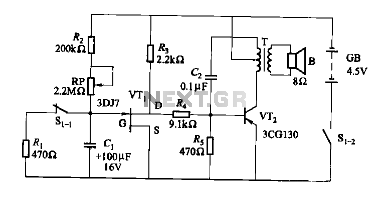
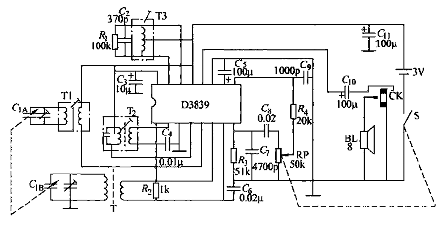
The darkroom circuit is designed for one-time exposure and emits an audible signal when the developing time is reached. This circuit can be utilized for photofinishing large timers and other applications. It comprises components such as FET VTi, resistors,...
A highly effective 1-watt FM transmitter circuit that is easy to construct. The circuit consists of four transistors: one functions as a stable oscillator, followed by a buffer stage to maintain frequency stability during adjustments. Next is a resonance...
This precise one-pulse-per-second clock is constructed using a few common components and is driven by a 50 or 60 Hertz mains supply, without any direct connection to it. It produces a beep or metronome-like click and/or a visible flash...

In a panic situation during the night when an intruder attempts to break into a house, this alarm system will assist by emitting a loud police siren to deter the intruder. The alarm system is designed to enhance home security...
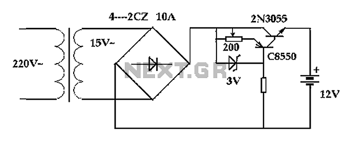
The circuit operates after a transformer, utilizing a bridge rectifier and conditioning for battery charging. The charging current transformer can be easily adjusted to provide approximately 12V at 100Ah battery charging. The required charging current is 10A, and a...
The circuit operates by utilizing a high-frequency section of the antenna to receive AM radio signals, amplifying radio-frequency signals at a selected vibration level of 465 kHz. The intermediate frequency (IF) signal is processed through an IF amplifier, followed...