
Classic car battery charging circuit diagram
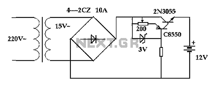
The described circuit is designed for charging a 100Ah battery efficiently. The system begins with a transformer that steps down the AC voltage to a manageable level for the rectification process. A transformer rated at 150VA with a secondary output of 15V AC is selected to ensure that it can deliver the necessary current of 10A for effective charging.
The bridge rectifier, composed of four diodes arranged to convert the AC voltage from the transformer into DC voltage, is crucial for providing a stable charging current. The output of the bridge rectifier is then smoothed using a large capacitor, which filters the rectified voltage to reduce ripple and maintain a stable DC output. This output is typically around 14.14V, which is suitable for charging lead-acid batteries.
To accommodate for different charging conditions, the circuit includes an adjustable charging current feature. This allows the user to set the desired charging rate, which, in this case, is designed to provide a charging current of 10A over a period of approximately 10 hours. This charging rate is essential to prevent overheating and overcharging of the battery, thereby extending its lifespan.
The design must also consider safety features, such as current limiting, to prevent damage to both the transformer and the battery during the charging process. The transformer is chosen to operate within safe limits, ensuring that it can handle the required load without overheating.
Overall, this circuit design emphasizes efficiency, safety, and adaptability for charging large capacity batteries in various applications, making it suitable for different energy storage needs. Circuit principle : circuit after transformer, bridge rectifier and conditioning on the battery charge, the charge current transformer can be adjusted simply give about 12v 100 AH battery charging, charging rate by 10 hours required charging current of 10A. Need 150VA transformer secondary AC voltage of 15V, limit current is 10A. Useful corresponding transformer substation to AC 10V, with a full-bridge rectifier coupled with the large capacitance of variable stable 14.14V.
Related Circuits
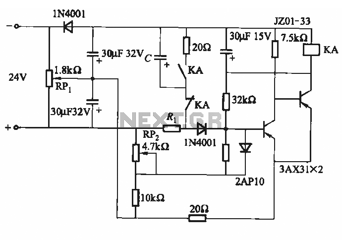
This circuit consists of five transistor time relay circuits designed for time relay exchange. It utilizes two different power supplies, maintaining the same circuit configuration. The delay time can be adjusted by modifying a potentiometer. The parameters for the...
The circuit diagram for a dynamic toy that produces eight sounds and five flashing lights is illustrated. It features the HFC3018 module, capable of generating eight distinct sounds, including step gunfire, aviation gunfire, game sight, telephone sight, bomb 1,...
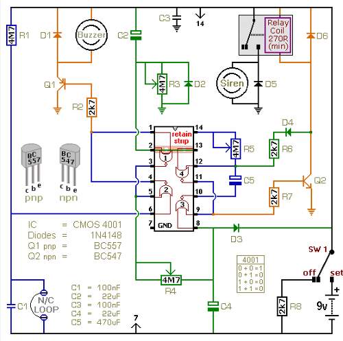
The following circuit illustrates a battery-powered burglar alarm sensor circuit. Features include foil tape and passive infrared sensors (PIRs), as well as magnetic reed contacts. This battery-powered burglar alarm sensor circuit is designed to provide an effective security solution for...

The trembler (motion-activated) switch triggers an alarm for 5 seconds before automatically turning off. The circuit has a timeout period of 10 seconds to allow the trembler switch to stabilize. The trembler switch circuit operates by detecting motion through a...
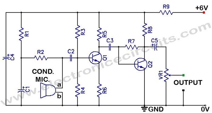
There is often a need for a sensitive sound pickup device, which can be utilized as a simple microphone or for more specialized applications such as a sound-operated alarm, a bugging device, or a sound-triggered flash for stop-action photography....
At low output power, up to 18 W, the device functions as a standard BTL amplifier. When a greater output voltage swing is necessary, the internal supply voltage is increased using external electrolytic capacitors. This momentarily elevated supply voltage...
Warning: include(partials/cookie-banner.php): Failed to open stream: Permission denied in /var/www/html/nextgr/view-circuit.php on line 713
Warning: include(): Failed opening 'partials/cookie-banner.php' for inclusion (include_path='.:/usr/share/php') in /var/www/html/nextgr/view-circuit.php on line 713