
1000w exchange regulator automatic voltage regulator circuit diagram
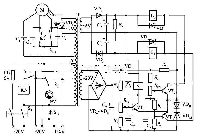
The circuit serves as an automatic voltage regulation system, designed to maintain a stable output voltage under varying load conditions. The main component, the automatic voltage regulator (T), adjusts the output voltage through feedback from the servo motor, which is mechanically linked to the output stage. This feedback loop ensures that any fluctuations in load do not affect the output voltage, providing a reliable power supply.
Transistors VT1 and VT2 (3DK9) are employed for switching and amplification purposes, ensuring efficient control of the voltage regulation process. The additional transistor VT3 (3AX818) further supports the regulation by enhancing the circuit's response to load changes.
The diode arrangement, including the 1N4002 and 1N4148 types, provides rectification and protection against reverse polarity, ensuring the circuit's longevity and reliability. The light-emitting diode (BT304) serves as an indicator, signaling the operational status of the circuit.
Capacitors are strategically placed throughout the circuit to filter voltage spikes and maintain stability. The selection of capacitors with varying capacitance values allows for effective smoothing of the output voltage, particularly under transient conditions.
The resistors are critical for setting biasing levels and controlling current flow within the circuit. The choice of metal film resistors for most components ensures precision and stability, which is vital for the performance of the voltage regulator.
Potentiometers RP1 and RP2 allow for manual adjustment of the circuit, enabling fine-tuning of the output voltage as required. The relays (JRK-13F) facilitate switching operations, controlling the power delivery to the load based on the feedback from the servo motor.
The AC contactor (522) provides isolation and protection for the circuit, while the voltmeter (85L1-0 to 250V) allows for monitoring the output voltage, ensuring that it remains within specified limits. Switches S1 and S2 enable user interaction with the circuit, providing options for manual control and operation.
Overall, this automatic voltage regulator circuit is designed for efficiency, reliability, and ease of use, making it suitable for various applications where voltage stability is critical. Circuit shown in Figure, T is auto voltage regulator. Its output fixed input end by a servo motor to automatically adjust the output remains constant. Transistor VTl, VT2: 3DK9 C, 65 ~ 85; VT3: 3AX818, 60 ~ 80; diode VD2, VD3, VD6 ~ VD9: 1N4002; VD4, VD5, VD10: 1N4148; VD11: IN4001; light-emitting diodes VD1: BT304; Zener diode VD12: 2CW119; capacitor C1: l F400V; C2, C3: 0.1 F250V; C4, C5: 220 F25V; C6: 470 F50V; C7, C8: 47 F50V; resistance Rl: 10k ; R2, R7: 510 ; R3, R6: 2.7k ; R4: 470 ; R5: 51 ; resistance in addition to the nominal power resistors Rl to select more than 3W power, other are selected 1/2 ~ 1/4W metal film resistors; potentiometer RPl, RP2: 1k ; relay Kl ~ K3: JRK-13F; AC contactor KA: 522; servo motor M: ND-D; voltmeter PV: 85L1-0 ~ 250V; switch S1KN3-3; S2: KN-2W1D; fuse FU: BGOP µ6-5A .
Related Circuits
This circuit is not a novelty, but it proved so useful, simple and cheap that it is worth building. When the positive (Red) probe is connected to a DC positive voltage and the Black probe to the negative, the...
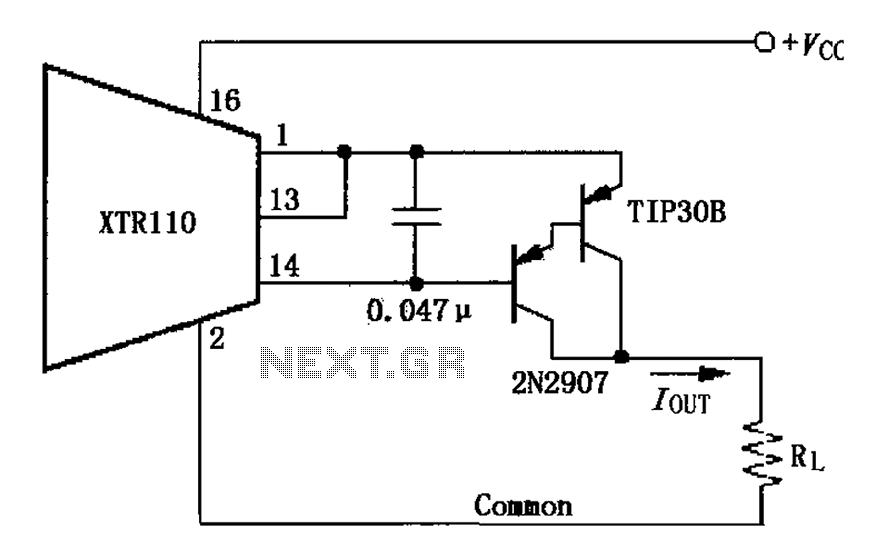
The circuit consists of two discrete PNP Darlington transistors that form the external PNP transistor QEXT circuit to enhance output current. The use of integrated Darlington transistors is not recommended, as the internal base-emitter resistor can introduce additional errors....
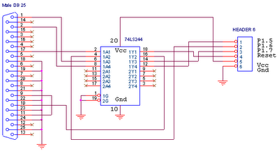
This circuit is designed for use with ATMEL Microcontroller ICs, specifically the AT89Sxx and ATMEGA series. It operates using the MISO, MOSI, SCK, and RESET signals. This circuit serves as a foundational interface for programming and communication with ATMEL microcontrollers,...
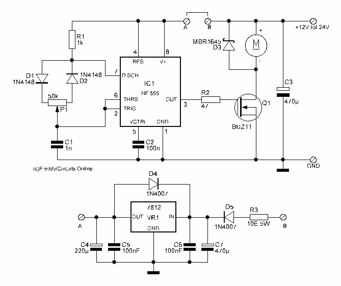
This circuit is 12 volt motors and lights well regulated. The scheme operates with PWM (Pulse Width Modulation). By IC1, a 555 is a square wave generated by a controllable duty cycle. This means that the width of the...
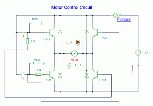
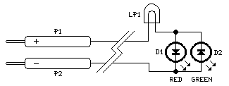
S1 and S2 are normally open, push-to-close, momentary switches. The diodes, which can be either red or green, serve solely to indicate the direction of operation. The TIP31 transistors may need to be adjusted based on the specifications of...
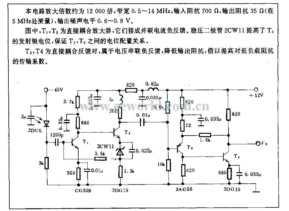
The amplification of this circuit is approximately 12,000 times, with a bandwidth ranging from 0.5 to 14 MHz. The input resistance is 700 ohms, while the output resistance is 35 ohms (measured at 5 MHz). The output noise level...
Warning: include(partials/cookie-banner.php): Failed to open stream: Permission denied in /var/www/html/nextgr/view-circuit.php on line 713
Warning: include(): Failed opening 'partials/cookie-banner.php' for inclusion (include_path='.:/usr/share/php') in /var/www/html/nextgr/view-circuit.php on line 713