
Mains Voltage Probe

This circuit functions as a simple voltage indicator, utilizing two Light Emitting Diodes (LEDs) and a bulb as a current limiter. The circuit is designed to provide visual feedback based on the polarity and type of voltage applied to the probes.
The circuit comprises a Red LED and a Green LED, which are connected in such a manner that the Red LED lights up when a positive DC voltage is detected at the positive probe (red) and the negative probe (black) is connected to ground or a negative supply. Conversely, when the polarity is reversed, the Green LED illuminates, indicating the presence of a negative voltage.
In the case of an AC voltage, both LEDs will activate simultaneously, providing a clear indication that alternating current is present. This dual LED configuration allows for quick identification of voltage type, which is particularly useful in troubleshooting electrical circuits.
The inclusion of a bulb in the circuit serves a dual purpose. Primarily, it acts as a current limiting device, ensuring that the LEDs do not exceed their maximum current rating of 40mA, especially when connected to high voltage AC sources up to 220V. The bulb's filament begins to glow at approximately 30V, which enhances the visual feedback of the circuit as the voltage increases. The filament's brightness correlates with the voltage level, allowing for a rough estimation of the voltage present.
This circuit is capable of detecting a voltage range from 1.8V to 230V, making it versatile for various applications. The simplicity and low cost of components make this circuit an attractive option for both hobbyists and professionals who require a straightforward voltage detection solution.This circuit is not a novelty, but it proved so useful, simple and cheap that it is worth building. When the positive (Red) probe is connected to a DC positive voltage and the Black probe to the negative, the Red LED will illuminate. Reversing polarities the Green LED will illuminate. Connecting the probes to an AC source both LEDs will go on. The bulb limits the LEDs current to 40mA @ 220V AC and its filament starts illuminating from about 30V, shining more brightly as voltage increases. Therefore, due to the bulb filament behavior, any voltage in the 1.8 to 230V range can be detected without
🔗 External reference
Related Circuits
This is a low-dropout (LDO) regulator circuit, constructed using only a single PNP transistor. This circuit is directly related to load current. At very low... The low-dropout (LDO) regulator is a crucial component in power management systems, providing a stable...
Occasionally, a small high-voltage power supply is required for various projects without the need for specialized transformers or specific chips. A simple circuit diagram for a classical step-up converter based on the widely used 555 timer was found online....
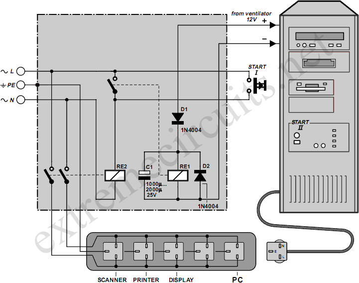
Downloading and CD-burning programs often offer the option to automatically shut down the PC upon completion of their tasks. However, this energy-saving feature is ineffective if all peripheral equipment remains connected to the mains and continues to consume power...
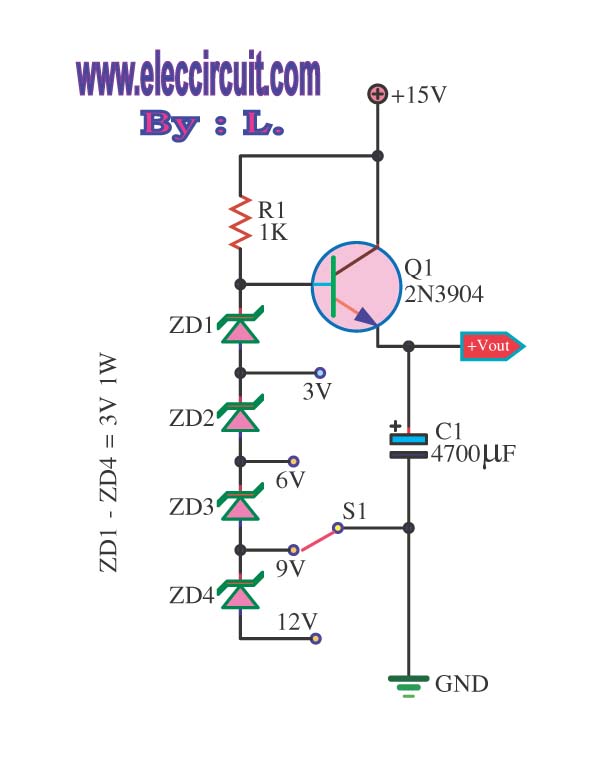
This is a DC regulator circuit that can provide multiple output voltages simply. It functions as a simple step-down DC converter and is designed with a fixed resistor R1. The described circuit operates as a DC voltage regulator, specifically designed...
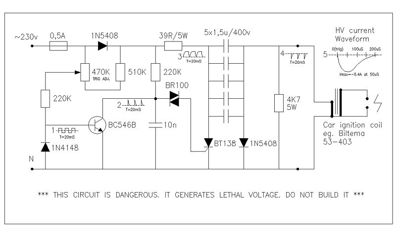
This circuit generates high voltage pulses from a 230 VAC line voltage. The drive end's swing comparator circuit was developed by the creator of this page. The working end is derived from a stroboscope trigger supply circuit. All circuits...

This document presents a set of plans for constructing an affordable, high-performance digital logic probe that can be assembled within a few hours. The design utilizes a plastic ballpoint pen as the chassis, providing a unique and stylish appearance....