
DC Motor Control Circuit

The circuit employs two momentary push-button switches, S1 and S2, which are utilized to control the direction of the motor that operates the curtain mechanism. When either switch is pressed, it completes the circuit, allowing current to flow through the TIP31 transistors, which act as electronic switches. The choice of the TIP31 transistor is critical as it must be capable of handling the motor's current requirements, particularly when the motor is under load.
The inclusion of diodes in the circuit serves a dual purpose. The first set of diodes, colored red or green, visually indicates the direction of the motor's rotation, providing an intuitive user interface. The second set of diodes, which are positioned in parallel with the motor, are specifically back EMF protection diodes. When the motor is turned off, it can generate a voltage spike due to the collapsing magnetic field, which can potentially damage the circuit components. The back EMF diodes safely dissipate this voltage spike, protecting the transistors and other sensitive components in the circuit.
For a typical application involving a 12V motor that draws 1 amp under load, the 1N4001 diodes are recommended for their adequate current and voltage ratings, ensuring reliable operation and protection. The overall design of this circuit emphasizes user control and safety, making it an effective solution for managing natural light in living spaces through manual curtain operation.Here, S1 and S2 are normally open, push to close, press button switches. The diodes can be red or green and are there only to indicate direction. You may need to alter the TIP31 transistors depending on the motor being used. Remember, running under load draws more current. This circuit was built to operate a small motor used for opening and closi ng a pair of curtains. As an advantage over automatic closing and opening systems, you have control of how much, or how little light to let into a room. The four diodes surriunding the motor, are back EMF diodes. They are chosen to suit the motor. For a 12V motor drawing 1amp under load, I use 1N4001 diodes. We aim to transmit more information by carrying articles. Please send us an E-mail to wanghuali@hqew. net within 15 days if we are involved in the problems of article content, copyright or other problems.
We will delete it soon. 🔗 External reference
Related Circuits
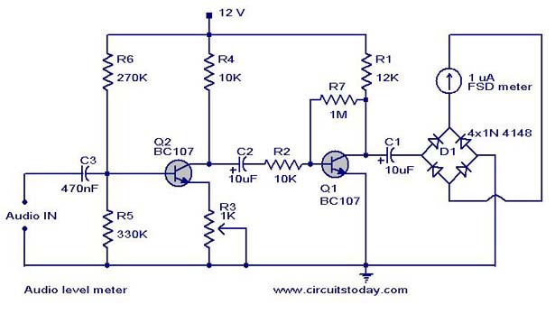
A simple audio level meter or Volume Unit (VU) level meter circuit with diagram and schematic. This sound level meter is designed using transistors with a flat frequency response in the range of 20Hz to 50kHz. The audio level meter...

This is a NiMH battery charger using the IC LTC4060, which is powerful, effective, and efficient. The LTC4060 IC specializes in NiMH battery charging, ensuring safe operation with features such as battery temperature protection during charging. It includes a...

Open loop speed control of a DC motor is implemented using the 8255 Digital I/O Controller chip in conjunction with a TCP/IP server-client application programmed in Visual Basic. The DAC0832 chip serves as the Digital to Analog Converter. This...

The SN754410 Dual Motor Control circuit is illustrated below. It is straightforward in design, with the PIC serving as the central processor. The main components included in the schematic are the 7805 voltage regulator, the 18F452 microcontroller, and the...
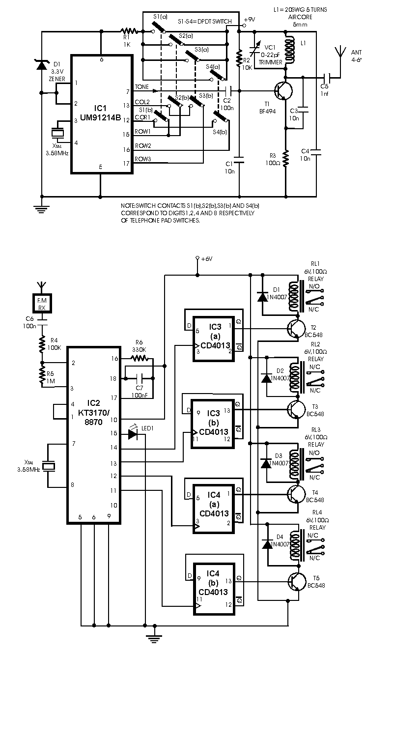
A radio remote control system utilizing DTMF (Dual-Tone Multi-Frequency) technology is presented. This circuit allows for the control of various electrical appliances through radio frequency signals. The described radio remote control system employs DTMF tones, which are generated by a...
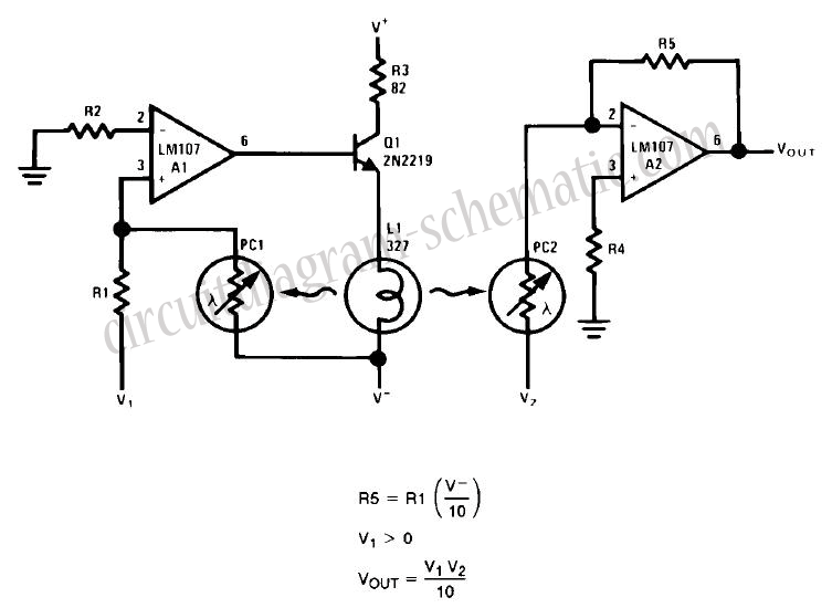
This circuit is a simple analog multiplier. The operation of the circuit can be understood by considering A2 as a controlled gain amplifier that amplifies V2, with its gain dependent on the ratio of the resistance of PC2 to...